Bose 901 Owner's guide - Page 6
Bose 901 Manual
 |
View all Bose 901 manuals
Add to My Manuals
Save this manual to your list of manuals |
Page 6 highlights
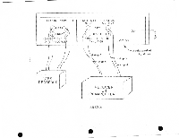
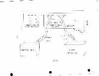
the Equalizer to the RIGHT or B channel TA-PE INPUT terminal on your preamplifier or receiver. (This preamplifier terminal may alternatively be labeled TAPE PLAYBACK or TAPE MONITOR. ) 4. Similarly, using a second cable connect the LEFT channel EQUALIZER OUTPUT terminal to the LEFT or A channel TAPE INPUT terminal on your preamplifier. 5. Using a third cable, connect the RIGHT channel EQUALIZER INPUT terminal on the Equalizer to the RIGHT or B channel TAPE OUTPUT terminal on your preamplifier. (This preamplifier terminal may alternatively be labeled RECORDER OUTPUT.) 6. Similarly, using the fourth cable connect the LEFT channel EQUALIZER INPUT terminal to the LEFT or A channel TAPE OUTPUT terminal on your preamplifier. 7. Connect the power cord from the Equalizer to an AC receptacle: You may prefer to use a receptacle or. your preamplifier or receiver so that the Equalizer will be automatically switched on and off by the power switch on the preamplifier or receiver. THE NEXT 5 STEPS ARE TESTS WHICH MUST BE PERFORMED TO INSURE PROPER OPERATION AND CORRECT INSTALLATION. 8. Place the TAPE switch on the Equalizer to the NORMAL position. Place the three frequency contour con- trols so they coincide with the indicated dots. These are the "normal" positions of the Equalizer controls. 9. Place the TAPE MONITOR or TAPE FUNCTION switch on your preamplifier to the NORMAL or OUT position. 10. Turn on the entire system except for the Equalizer, which should be turned off. 11. Play your system as you normally would using a phono- graph or AM-FM source (NOT a tape recorder) to be sure it is - 5- •
-
 1
1 -
 2
2 -
 3
3 -
 4
4 -
 5
5 -
 6
6 -
 7
7 -
 8
8 -
 9
9 -
 10
10 -
 11
11 -
 12
12 -
13
-
14
-
15
 |
 |
