Bose 901 Owner's guide - Page 8
Bose 901 Manual
 |
View all Bose 901 manuals
Add to My Manuals
Save this manual to your list of manuals |
Page 8 highlights
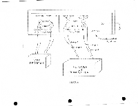
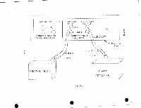
Equalizer to the RIGHT or B channel OUTPUT terminal on the tape recorder. 3. Similarly, connect the LEFT channel TAPE IN terminal on the Equalizer to the LEFT or A channel OUTPUT on the tape recorder. 4. Connect the RIGHT channel TAPE OUT terminal on the Equalizer to the RIGHT or B channel INPUT terminal on the recorder. 5. Similarly, connect the LEFT channel TAPE OUT on the Equalizer to the LEFT or A channel INPUT on the recorder. These connections are illustrated in Figure 2. Installation of the recorder is now complete. The TAPE switch on the Equalizer replaces the TAPE MONITOR switch on the preamplifier or receiver and performs the identical function. Consult your amplifier manual for a description of its use. VI. Alternative Method: Connecting the 901 • Active Equalizer Between a Preamplifier and a Power Amplifier. If you have a separate preamplifier and power amplifier, then the Equalizer may alternatively be inserted between these pieces of equipment. With this method of connection, the preamplifier is used and connected to other components of your system (except for your power amplifier) as if the Equalizer were not present. If this connection is desired, use the following procedure and refer to Figure 3. 1. Turn all power off. 2. If your system is already installed, then remove the two audio cables connecting the INPUT terminals on your power amplifier to the OUTPUT terminals on your preamp (These preamp terminals may alternatively be labeled PREAMP OUT or OUTPUT TO AMPLIFIER). 3. Using one of the cables supplied with the Equalizer or one of the cables you have just disconnected, connect - 7- •
-
 1
1 -
2
-
 3
3 -
 4
4 -
 5
5 -
 6
6 -
 7
7 -
 8
8 -
 9
9 -
 10
10 -
 11
11 -
 12
12 -
 13
13 -
14
-
15
 |
 |