Bose Acoustimass Powered Owner's guide - Page 8
connections
 |
View all Bose Acoustimass Powered manuals
Add to My Manuals
Save this manual to your list of manuals |
Page 8 highlights
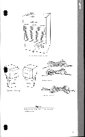
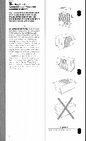
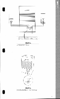
3 Connect the cube arrays to the Acoustimass' bass module. Lcok at the woo supplted speaker cables. Each cable has two wires. The positive ( +) wire will be indicated by one of the following: • Ribbed surface • Red collar • Stripe The solid wire is negative (-). The positive and negative wires correspond respectively to the positive (red) and negative (black) terminals on the backs of the cube arrays and the Acoustimass hack module (Figure 5). The wires should always be connected to their corresponding terminals, positive to positive, negative to negative. a. Connect the end of one speaker cable to the terminals on the rear of the right cube array, and the other end of the cable to the OUTPUT terminals on the rear of the Acoustimass bass module marked TO RIGHT CUBE ARRAY. To do so. simply push each terminal tab down, insert the end of the appropriate wire into the exposed hole, and release the tab to secure the wire into place (see Figure 4). b. Repeat to conned the left cube array to the OUTPUT terminal on the Acoustimass bass module marked TO LEFT CUBE ARRAY. c. Check all your connections to make sure they are wired positive to positive( + to + ) and negative to negative(- to -). Incorrect wiring will affect the stereo image. Also, check to make sure that no strands of wire from any terminal are brushing against any other terminal. Such "bridged" wires create short circuits that may damage your Acoustimass powered speaker system. Figure 5 illustrates a finished system hookup. 4 Plug in the AC power (mains) coIrId your lifestylenA music center r °the music source) 5 Set the voltage selector switch (on International models of the Acoustimass powered speaker system) to the correct voltage setting for your area (Figure 4A). Plug in the Acoustimass bass module's power (mains) cord. On models equipped with a POWER switch (Figure 6), turn this switch ON (I) at this time. Turn on the music and enjoy! FIGHT Genera MTN era _ )LEI H vs, Figure 4. Hew to properly connect wires to a terminal 120V 220-240V VOLTAGE SELECTOR Figure 4A. Important: The voltage selector switch must be set correctly for your area. Use 120V for North and Central America, and 220-240V for Europe, UK, and Australia. 7
-
 1
1 -
2
-
 3
3 -
 4
4 -
 5
5 -
 6
6 -
 7
7 -
 8
8 -
 9
9 -
 10
10 -
 11
11 -
 12
12 -
 13
13 -
14
-
15
-
16
 |
 |
