Boss Audio BV9982I User Manual in English - Page 8
Speaker Setup, Downmix, 23.6 Digital Setup, Op Mode, Dynamic Range, Dual Mono - systems
 |
View all Boss Audio BV9982I manuals
Add to My Manuals
Save this manual to your list of manuals |
Page 8 highlights
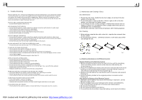
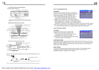
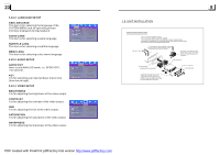
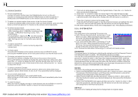
1.7 Wires Connection Description Description of Wires Connection Fixing Screw Bolt Wiring Connecting Socket 1 GREEN Wiring Connecting Socket 2 PARKING LINE WHITE Black REVERSAL LINE USB LINE IN Radio Antenna jack Black Black 1. Parking wire must be connected. And the parking brake must be engaged in order for the monitor to work. 2. Use the clip end of the Ground Wire provided by manufacturer to connect Mounting Screw, using the other end of the Ground Wire to connect the negative pole of the power source. Otherwise, the video on screen maybe flashes. Description of the Wiring Diagram for Socket 1 ISO CONNECTOR WIRING CONNECTING SOCKET 1 WIRING CONNECTING PLUG 1 YELLOW MEMORY B+ FUSED BLACK(GND) FILTER BOX 1A RED & 10 A IGNITION SWITCH FUSES BLUE AUTO ANT WOOFER LINE OUT GREEN BLACK FRONT AUDIO RCA OUT RED R WHITE L FRONT WHITE GRAY FRONT LEFT SP WHITE / BLACK GREEN GRAY / BLACK VIOLET RIGHT SP REAR GREEN / BLACK VIOLET / BLACK REAR NOTES: 1. Only speakers with 4 ohms impedance may be used. 2. Ensure that the blue auto antenna cable does not make contact with any ground connection. Description of the Wiring Diagram for Socket 2 RED R WHITE L YELLOW VIDEO YELLOW YELLOW YELLOW BROWN AV RCA AUX IN GREY VIDEO RCA OUT BLACK REAR VIEW CAMERA WIRING CONNECTING SOCKET 2 WIRING CONNECTING PLUG 2 GREY REAR AUDIO RCA OUT BLACK RED R WHITE L IPod IN Description of Connecting the Parking Brake Line to the Parking Brake System Built in a Car Parking brake Parking brake wire(Green) Parking brake switch (inside the car) To metallic body or chassis of the car NOTE: after connecting the Parking Line, the video on the small monitor of the front panel will be display only after br aking the car. 5.23.5 SPEAKER SETUP DOWNMIX This is for selecting your desired sound effect when there is no center speaker and subwoofer. There are 3 modes: LT/RT, STEREO, VSS. LT/RT: When playing a disc with PRO LOGIC stereo effect, choose the item, so it will output audio signal with vivid theatre effect. STEREO: If you choose the item, when outputting audio signal with 5.1 channels, it will output the left and right channels of signal ; when outputting audio signal with 2 channels, it will output the common 2 channels of stereo signal. VSS: If you choose the item, when playing a disc recorded with 5.1 channels, the main channel speakers can output audio signal with VSS effect. 5.23.6 DIGITAL SETUP OP MODE This is for selecting audio output mode LINE OUT: It can linearly compress the audio signal. So the volume level is lower. You should select the item at night. RF REMOD: It can make the volume level higher. You should select it at daylight. DYNAMIC RANGE After selecting the compression mode of LINE OUT, set the item, so you can adjust the linear compression ratio. If you set it to be FULL, the Peak-to-Peak value of the audio signal is the minimum; if you set it to be OFF, the Peak-toPeak value is the maximum. DUAL MONO This is for selecting a desired audio output mode for left and right signals. It is mainly for Karaoke of Ac3. There are 4 modes in all as follows: STEREO, MONO L, MONO R, MIX MONO. PDF created with FinePrint pdfFactory trial version http://www.pdffactory.com
-
 1
1 -
2
-
 3
3 -
 4
4 -
 5
5 -
 6
6 -
 7
7 -
 8
8 -
 9
9 -
 10
10 -
 11
11 -
 12
12 -
 13
13 -
14
-
15
-
16
 |
 |
