Brother International BAS-342G PS Instruction Manual - English - Page 17
Installing the gas spring, Bolts [4 pcs.]
 |
View all Brother International BAS-342G PS manuals
Add to My Manuals
Save this manual to your list of manuals |
Page 17 highlights
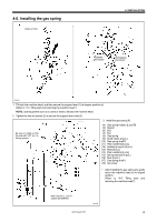
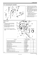
4-6. Installing the gas spring Crane or hoist 4. INSTALLATION Engaging the stopper Disengaging the stopper 2744B 1. Tilt back the machine head, and then secure the support lever (1) at stopper position (a). (Refer to "4-5. Tilting back and returning the machine head".) NOTE: Use equipment such as a crane or hoist to tilt back the machine head. 2. Tighten the two set screws (2) to secure the support lever shaft (3). 3. Install the gas spring (8). Be sure to install so that the side with "UP" on it is facing upward. (4) Gas spring holders [L and R] (5) Spacer (6) Bolt (7) Nut (8) Gas spring (9) Shaft collars [2 pcs.] (10) Gas spring shaft D (11) Plain washers [2 pcs.] (12) Retaining rings E [2 pcs.] (13) Bolts [4 pcs.] (14) Plain washers [4 pcs.] (15) Spring washers [4 pcs.] (16) Nuts [4 pcs.] (17) Gas spring shaft U (18) Set screw * After installing the gas spring (8), gently return the machine head to its original position. (Refer to "4-5. Tilting back and returning the machine head".) Note that the L and R shapes are different. 2915B BAS-342G PS 8
-
 1
1 -
2
-
3
-
4
-
5
-
6
-
7
-
8
-
9
-
10
-
11
-
 12
12 -
 13
13 -
 14
14 -
 15
15 -
 16
16 -
 17
17 -
 18
18 -
 19
19 -
 20
20 -
 21
21 -
 22
22 -
23
-
24
-
25
-
26
-
27
-
28
-
29
-
30
-
31
-
32
-
33
-
34
-
35
-
36
-
37
-
38
-
39
-
40
-
41
-
42
-
43
-
44
-
45
-
46
-
47
-
48
-
49
-
50
-
51
-
52
-
53
-
54
-
55
-
56
-
57
-
58
-
59
-
60
-
61
-
62
-
63
-
64
-
65
-
66
-
67
-
68
-
69
-
70
-
71
-
72
-
73
-
74
-
75
-
76
-
77
-
78
-
79
-
80
-
81
-
82
-
83
-
84
-
85
-
86
 |
 |
