Brother International BES-916AC Instruction Manual - English - Page 151
ERROR E5 to ERROR FF frequently, Wiper solenoid does not operate.
 |
View all Brother International BES-916AC manuals
Add to My Manuals
Save this manual to your list of manuals |
Page 151 highlights
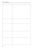
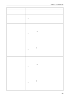
Chapter 10 Troubleshooting Symptom Measures ERROR E5 to ERROR FF frequently • Replace the main PCB with a new one. occur. All solenoids of head do not operate. • Refer to the block diagram showing cable connections and check fuse F2 on the power supply PCB. If it is blown, replace it with a new one. The 60v circuit is faulty if the fuse is blown immediately after turning on the power even after replacing the fuse. Jump solenoid does not operate. • Check to see if connection from the jump solenoid to connector P10 of the head PCB is proper. • Check the resistance value of the jump solenoid which does not operate with the connector section. The normal resistance value is approximately 185Ω. If it is faulty, replace the solenoid with a new one. In this case, the head PCB may also be faulty. Also replace the head PCB with a new one if it does not operate properly even after replacing the solenoid. • Replace the head PCB with a new one. Wiper solenoid does not operate. • Check to see if connection from the wiper solenoid to connector P11 of the head PCB is proper. • Check the resistance value of the wiper solenoid which does not operate with the connector section. The normal resistance value is approximately 28Ω. If it is faulty, replace the solenoid with a new one. In this case, the head PCB may also be faulty. Also replace the head PCB with a new one if it does not operate properly even after replacing the solenoid. • Replace the head PCB with a new one. Pickker solenoid does not operate. • Check to see if connection from the pickker solenoid to connector P8 of the head PCB is proper. • Check the resistance value of the pickker solenoid which does not operate with the connector section. The normal resistance value is approximately 426Ω. If it is faulty, replace the solenoid with a new one. In this case, the head PCB may also be faulty. Also replace the head PCB with a new one if it does not operate properly even after replacing the solenoid. • Replace the head PCB with a new one. Thread trimmer solenoid does not operate. • Check to see if connection from the thread trimmer solenoid to connector P20 of the main PCB is proper. • Check the resistance value of the thread trimmer solenoid which does not operate with the connector section. The normal resistance value is approximately 27Ω. If it is faulty, replace the solenoid with a new one. In this case, the main PCB may also be faulty. Also replace the main PCB with a new one if it does not operate properly even after replacing the solenoid. • Replace the main PCB with a new one. BES-916AC • BES-1216AC 149
-
 1
1 -
2
-
3
-
4
-
5
-
6
-
7
-
8
-
9
-
10
-
11
-
12
-
13
-
14
-
15
-
16
-
17
-
18
-
19
-
20
-
21
-
22
-
23
-
24
-
25
-
26
-
27
-
28
-
29
-
30
-
31
-
32
-
33
-
34
-
35
-
36
-
37
-
38
-
39
-
40
-
41
-
42
-
43
-
44
-
45
-
46
-
47
-
48
-
49
-
50
-
51
-
52
-
53
-
54
-
55
-
56
-
57
-
58
-
59
-
60
-
61
-
62
-
63
-
64
-
65
-
66
-
67
-
68
-
69
-
70
-
71
-
72
-
73
-
74
-
75
-
76
-
77
-
78
-
79
-
80
-
81
-
82
-
83
-
84
-
85
-
86
-
87
-
88
-
89
-
90
-
91
-
92
-
93
-
94
-
95
-
96
-
97
-
98
-
99
-
100
-
101
-
102
-
103
-
104
-
105
-
106
-
107
-
108
-
109
-
110
-
111
-
112
-
113
-
114
-
115
-
116
-
117
-
118
-
119
-
120
-
121
-
122
-
123
-
124
-
125
-
126
-
127
-
128
-
129
-
130
-
131
-
132
-
133
-
134
-
135
-
136
-
137
-
138
-
139
-
140
-
141
-
142
-
143
-
144
-
145
-
 146
146 -
 147
147 -
 148
148 -
 149
149 -
 150
150 -
 151
151 -
 152
152 -
 153
153 -
 154
154 -
 155
155 -
 156
156 -
157
 |
 |
