Brother International Innov-is BQ950 Operation Manual - Page 10
Getting Ready
 |
View all Brother International Innov-is BQ950 manuals
Add to My Manuals
Save this manual to your list of manuals |
Page 10 highlights
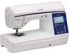
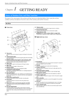
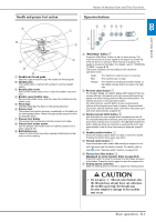
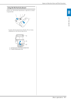
Names of Machine Parts and Their Functions 1 Chapter GETTING READY Names of Machine Parts and Their Functions The names of the various parts of the machine and their functions are described below. Before using the machine, carefully read these descriptions to learn the names of the machine parts and their locations. Machine ■ Front view a b c de o n m f g h i C Thread cutter Pass the threads through the thread cutter to cut them. D Needle threader lever Use the needle threader lever to thread the needle. E Thread tension dial (Equipped on some models. Refer to page B-8) Use the dial to adjust the upper thread tension. (page B-40) ■ Right-side/rear view a b c j l k 1 Top cover Open the top cover to place the spool of thread on the spool pin. 2 Thread guide plate Pass the thread around the thread guide plate when threading the upper thread. 3 Bobbin winding thread guide and pretension disk Pass the thread under this thread guide and around the pretension disk when winding the bobbin thread. 4 Spool cap Use the spool cap to hold the spool of thread in place. 5 Spool pin Place a spool of thread on the spool pin. 6 Bobbin winder Use the bobbin winder when winding the bobbin. 7 LCD (liquid crystal display) Settings for the selected stitch and error messages appear in the LCD. (page B-11) 8 Operation panel From the operation panel, stitch settings can be selected and edited, and operations for using the machine can be selected (page B-4). 9 Knee lifter mounting slot Insert the knee lifter into the knee lifter mounting slot. 0 Knee lifter Use the knee lifter to raise and lower the presser foot. (page B-45) A Operation buttons and sewing speed controller Use these buttons and the slide to operate the machine. (page B-3) B Flat bed attachment Insert the presser foot accessory tray into the accessory compartment of the flat bed attachment. Remove the flat bed attachment when sewing cylindrical pieces such as sleeve cuffs. i d h e f g 1 Handwheel Turn the handwheel toward you (counterclockwise) to raise and lower the needle to sew one stitch. 2 Handle Carry the machine by its handle when transporting. 3 Presser foot lever Raise and lower the presser foot lever to raise and lower the presser foot. 4 Feed dog position switch Use the feed dog position switch to lower the feed dogs. 5 Main power switch Use the main power switch to turn the machine on and off. 6 Power supply jack Insert the plug on the power supply cord into the power supply jack. 7 Foot controller Depress the foot controller to control the speed of the machine. (page B-36) 8 Air vent The air vent allows the air surrounding the motor to circulate. Do not cover the air vent while the machine is being used. 9 Foot controller jack Insert the plug on the end of the foot controller cable into the foot controller jack. B-2
-
 1
1 -
2
-
3
-
4
-
 5
5 -
 6
6 -
 7
7 -
 8
8 -
 9
9 -
 10
10 -
 11
11 -
 12
12 -
 13
13 -
 14
14 -
 15
15 -
16
-
17
-
18
-
19
-
20
-
21
-
22
-
23
-
24
-
25
-
26
-
27
-
28
-
29
-
30
-
31
-
32
-
33
-
34
-
35
-
36
-
37
-
38
-
39
-
40
-
41
-
42
-
43
-
44
-
45
-
46
-
47
-
48
-
49
-
50
-
51
-
52
-
53
-
54
-
55
-
56
-
57
-
58
-
59
-
60
-
61
-
62
-
63
-
64
-
65
-
66
-
67
-
68
-
69
-
70
-
71
-
72
-
73
-
74
-
75
-
76
-
77
-
78
-
79
-
80
-
81
-
82
-
83
-
84
-
85
-
86
-
87
-
88
-
89
-
90
-
91
-
92
-
93
-
94
-
95
-
96
-
97
-
98
-
99
-
100
-
101
-
102
-
103
-
104
-
105
-
106
-
107
-
108
-
109
-
110
-
111
-
112
-
113
-
114
-
115
-
116
-
117
-
118
-
119
-
120
-
121
-
122
-
123
-
124
-
125
-
126
-
127
-
128
-
129
-
130
-
131
-
132
-
133
-
134
-
135
-
136
-
137
-
138
-
139
-
140
-
141
-
142
-
143
-
144
 |
 |
