Brother International KM-430B Network Users Manual - English - Page 5
Mechanism
 |
View all Brother International KM-430B manuals
Add to My Manuals
Save this manual to your list of manuals |
Page 5 highlights
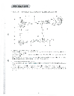
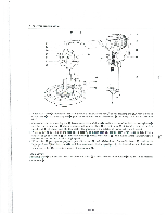
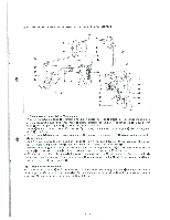
MECHANISM 1 NEEDL BAR, THREAD TAKE-UP LEVER, LOWER SHAFT, SHUTTLE MECHANISMS 0 0 A 0 9 0 0 0 -- 0 ®- 0 -- (1) Needle Bar and Thread Take-up Lever Mechanism I . When pulley 0 turns in the arrow direction, its rotating motion is conveyed to counter weight 0 which is connected to upper shaft O. 2. Needle bar crank is attached to counter weight so that needle bar clamp() is moved up and down via needle bar crank rod 0. 3. Needle bar 0, which is gripped by needle bar clamp 0, is guided by needle bar bushing U 0, needle bar bushing D and needle bar guide slide block m' smoothly run up and down. 0 00 (2) Lower Shaft and Shuttle Mechanism 4. When pulley 0 turns in the arrow direction, crank rod ID moves up and down via the crank part ® of the upper ®, J. shaft. 5. The lower end of crank rod m is connected to rock gear and rocks about rock gear shaft ® 6. Rock gear ID engages lower shaft gear ID which is fixed to lower shaft (D. and turns lower shaft m one half of a turn. Similarly, its motion is conveyed to driver 0 attached to the tip of lower shaft 0 to drive shuttle one half of a turn.
-
 1
1 -
 2
2 -
 3
3 -
 4
4 -
 5
5 -
 6
6 -
 7
7 -
 8
8 -
 9
9 -
 10
10 -
 11
11 -
12
-
13
-
14
-
15
-
16
-
17
-
18
-
19
-
20
-
21
-
22
-
23
-
24
-
25
-
26
-
27
-
28
-
29
-
30
-
31
-
32
-
33
-
34
-
35
-
36
-
37
-
38
-
39
-
40
-
41
-
42
-
43
-
44
-
45
-
46
 |
 |
