Brother International KM-430B Network Users Manual - English - Page 7
Power, Clamp, Lifter, Thread, Wiper, Mechanisms
 |
View all Brother International KM-430B manuals
Add to My Manuals
Save this manual to your list of manuals |
Page 7 highlights
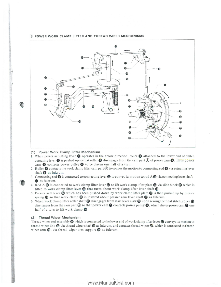
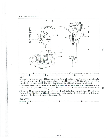
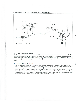
0 0 0 Q 00 3 POWER WORK CLAMP LIFTER AND THREAD WIPER MECHANISMS -- 0 0 -- 0 A / B O- ®-- 0 (1) Power Work Clamp Lifter Mechanism I. When power actuating lever 0 operates in the arrow direction, roller attached to the lower end of clutch actuating lever is pushed up so that roller disengages from the cam part Q of power cam 0. Thus power cam contacts power pulley 0 to be driven one half of a turn. 2. Roller 0 contacts the work clamp lifter cam part 0 to convey the motion to connecting rod 0 via actuating lever shaft as fulcrum. 3. Connecting rod 0 is connected to connecting lever to convey its motion to rod A e via connecting lever shaft (I) as fulcrum. 4. Rod A 0 is connected to work clamp lifter lever to lift work clamp lifter plate m via slide block which is fitted to work clamp lifter lever e that turns about work clamp lifter lever shaft m. 5. Presser arm lever m which has been pushed down by work clamp lifter plate Q is then pushed up by presser spring 0 so that work clamp 4) is lowered about presser arm lever shaft ito as fulcrum. 6. When work clamp lifter roller shafts disengages from start lever claw upon sewing the final stitch, roller disengages from the cam part 0 so that power cam 0 contacts power pulley Q, which drives power cam 0 one half of a turn to lift work clamp 11). (2) Thread Wiper Mechanism Thread wiper rod assembly 10 which is connected to the lower end of work clamp lifter lever aro conveys its motion to thread wiper link 0 via thread wiper shafts as fulcrum, and actuates thread wiper e, which is connected to thread wiper arm 0, via thread wiper arm support Q as fulcrum.
-
 1
1 -
 2
2 -
 3
3 -
 4
4 -
 5
5 -
 6
6 -
 7
7 -
 8
8 -
 9
9 -
 10
10 -
 11
11 -
 12
12 -
13
-
14
-
15
-
16
-
17
-
18
-
19
-
20
-
21
-
22
-
23
-
24
-
25
-
26
-
27
-
28
-
29
-
30
-
31
-
32
-
33
-
34
-
35
-
36
-
37
-
38
-
39
-
40
-
41
-
42
-
43
-
44
-
45
-
46
 |
 |