Brother International KM-430B Network Users Manual - English - Page 8
ID ID, Length, Mechanism, Roller
 |
View all Brother International KM-430B manuals
Add to My Manuals
Save this manual to your list of manuals |
Page 8 highlights
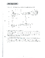
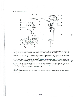
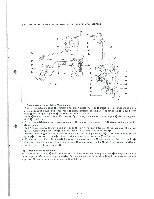
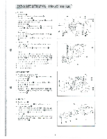
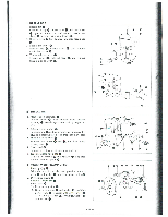
L FEED MECHANISM 0 ID ID "C• -0 --o -0 (1 ) Tack Width Mechanism I When upper shaft 0 turns in the arrow direction, worm wheel 0 which is connected to vertical shaft 0 rotates in the arrow direction. Change gear W 0 in mesh with the lower end of vertical shaft 0 comes into mesh with change gear C 0 which is engaged with feed cam 0 so that feed cam 0 rotates similarly in the arrow direction. 2. Roller 0 fits in the groove of feed cam 0 to convey the rocking motion to tack width feed lever 0. Tack width e ® regulator lever 0, which is connected to tack width feed lever 0, similarly rocks. 3. Tack width lever 0 is connected to tack width regulator lever 0 with nut so that it moves feed guide back and forth about tack width lever shaft ® as fulcrum. (2) Tack Length Mechanism 4. Roller ID fits in the groove on the underside of feed cam 0 to convey the rocking motion to back length feed lever 0 about tack length feed lever shaft op as fulcrum. e 5. Tack length regulator lever 0 is connected to tack length feed lever 0 with nut so that it rocks tack length ®. ®' lever Similarly, slide block fits into the slot of feed guide go to move feed guide sidewise. 6. The combination of the motions mentioned in Paragraphs 3 and 5 produces a sewing pattern.
-
 1
1 -
2
-
 3
3 -
 4
4 -
 5
5 -
 6
6 -
 7
7 -
 8
8 -
 9
9 -
 10
10 -
 11
11 -
 12
12 -
 13
13 -
14
-
15
-
16
-
17
-
18
-
19
-
20
-
21
-
22
-
23
-
24
-
25
-
26
-
27
-
28
-
29
-
30
-
31
-
32
-
33
-
34
-
35
-
36
-
37
-
38
-
39
-
40
-
41
-
42
-
43
-
44
-
45
-
46
 |
 |
