Brother International KM-430B Network Users Manual - English - Page 6
Clutch, Mechanism, Lever
 |
View all Brother International KM-430B manuals
Add to My Manuals
Save this manual to your list of manuals |
Page 6 highlights
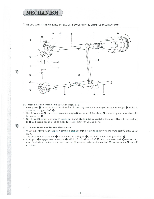
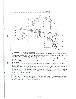
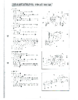
[2 CLUTCH MECHANISM 0 0 A 0- 0 o- 0- 0 0 0 8 0 0 0 --" 0 I . When start le\ er 0 operates in the arrow direction, the low speed part ® of ball presser plate 0, which is fixed to clutch lever 0 N is connecting rod 0, gets in line with the center of steel ball 0 to convey the power to the upper shaft. 2. One end of clutch connecting rod 0 is connected to clutch lever 0 , and the other end to clutch actuating lever 0 to drive clutch cam lever 0 about clutch actuating lever shaft 0 so that roller (CI at its end goes up on the low e. speed part 0 of clutch cam This makes the machine sew 2 stitches at low speed from the start. ® 3. When roller 0 goes up on the high speed part © of clutch cam 0, control cam lever roller falls from a projected part of feed cam Q) so that roller holder ® comes under roller C). This makes the machine sew up to 4 ® stitches before the final stitch at high speed. 4. When roller goes up on a projected part of feed cam 0, roller is released from roller holder 0 to fall on the high speed part © of clutch cam m, and then moves onto the low speed part ®. As the machine sews 4 stitches at low speed, roller Q) gets into a recess of clutch cam (1). (Stop Lever) ® When stop lver ®. clutch cam is pushed in the arrow direction, roller® is released from roller holder® and gets into a recess of
-
 1
1 -
 2
2 -
 3
3 -
 4
4 -
 5
5 -
 6
6 -
 7
7 -
 8
8 -
 9
9 -
 10
10 -
 11
11 -
 12
12 -
13
-
14
-
15
-
16
-
17
-
18
-
19
-
20
-
21
-
22
-
23
-
24
-
25
-
26
-
27
-
28
-
29
-
30
-
31
-
32
-
33
-
34
-
35
-
36
-
37
-
38
-
39
-
40
-
41
-
42
-
43
-
44
-
45
-
46
 |
 |
