Bushnell 201930 User Manual - Page 6
Optical Design - tour v2 with pinseeker
 |
View all Bushnell 201930 manuals
Add to My Manuals
Save this manual to your list of manuals |
Page 6 highlights
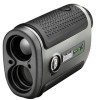
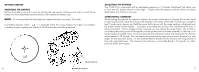
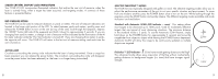
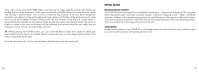
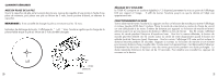
Once in this mode, press the POWER button to turn the unit on. Next, align the aiming circle reticle onto the flag that you want distance to. Next, press and hold the POWER button and move the laser slowly over the flag or desired object until a circle surrounds the flag indicator. If the laser beam recognized more than one object (i.e. flag and background trees), distance of the flag will be displayed and a circle will surround the PinSeeker indicator informing the user that distance to the flag (i.e. closer object) is being displayed in the LCD (as seen below). There may be times when only the laser beam only sees one object in its path. In this case, the distance will be displayed, but because more than one object was not acquired, a circle will not surround the flag indicator. TIP: While pressing the POWER button, you can move the device slowly from object to object and intentionally force the laser to hit multiple objects to ensure that you are only displaying the closest of the objects recognized by the laser. Once the device has shut off, the unit will always default back to the last mode used. OPTICAL DESIGN Magnification and Coatings The TOUR V2 features 5x magnification and Multi-Coated optics. A liquid crystal display (LCD) is mounted within the optical system and when activated, displays a reticle for targeting, yards / meters, and Mode indicators. Inherent in the manufacturing process are small black spots that appear in the optical system. These are a natural characteristic of the LCD and cannot be fully eliminated in the manufacturing process. They do not affect the distancing performance of the unit. TRIPOD MOUNT Molded into the bottom of your TOUR V2 is a threaded tripod mount that will allow you to attach a tripod for a more stable operation during long periods of use. 10 11
-
 1
1 -
 2
2 -
 3
3 -
 4
4 -
 5
5 -
 6
6 -
 7
7 -
 8
8 -
 9
9 -
 10
10 -
 11
11 -
 12
12 -
13
-
14
-
15
-
16
-
17
-
18
-
19
-
20
-
21
-
22
-
23
-
24
-
25
-
26
-
27
-
28
-
29
-
30
-
31
-
32
-
33
-
34
-
35
-
36
-
37
-
38
-
39
-
40
-
41
-
42
-
43
-
44
 |
 |