Canon 2080B001 XL H1S / XL H1A Instruction Manual - Page 87
Using the COMPONENT OUT Terminal, Using the HDV/DV Terminal, and close the menu.
 |
UPC - 013803079685
View all Canon 2080B001 manuals
Add to My Manuals
Save this manual to your list of manuals |
Page 87 highlights
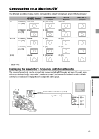
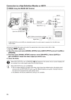
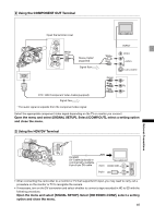
2 Using the COMPONENT OUT Terminal Open the terminal cover White Red Stereo Cable* (supplied) Signal flow White Red INPUT VIDEO L AUDIO R S (S1)-VIDEO DTC-1000 Component Video Cable (supplied) Signal flow Green Y Blue Pb Red Pr * The audio signal is separate from the component video signal Select the appropriate component video signal depending on the TV or monitor you connect. Open the menu and select [SIGNAL SETUP]. Select [COMP.OUT], select a setting option and close the menu. 3 Using the HDV/DV Terminal External Connections CV-250F DV Cable (optional) or commercially available 6 pin-6 pin DV cable 4-pin 6-pin • When connecting the camcorder to a monitor or TV that supports DV input, you may need to carry out a procedure on the monitor or TV to recognize the camera. • If necessary, turn on the DV conversion and select whether to convert a tape recorded in HD to SD with the following procedure. Open the menu and select [SIGNAL SETUP]. Select [HD DOWN-CONV], select a setting option and close the menu. 87
-
 1
1 -
2
-
3
-
4
-
5
-
6
-
7
-
8
-
9
-
10
-
11
-
12
-
13
-
14
-
15
-
16
-
17
-
18
-
19
-
20
-
21
-
22
-
23
-
24
-
25
-
26
-
27
-
28
-
29
-
30
-
31
-
32
-
33
-
34
-
35
-
36
-
37
-
38
-
39
-
40
-
41
-
42
-
43
-
44
-
45
-
46
-
47
-
48
-
49
-
50
-
51
-
52
-
53
-
54
-
55
-
56
-
57
-
58
-
59
-
60
-
61
-
62
-
63
-
64
-
65
-
66
-
67
-
68
-
69
-
70
-
71
-
72
-
73
-
74
-
75
-
76
-
77
-
78
-
79
-
80
-
81
-
 82
82 -
 83
83 -
 84
84 -
 85
85 -
 86
86 -
 87
87 -
 88
88 -
 89
89 -
 90
90 -
 91
91 -
 92
92 -
93
-
94
-
95
-
96
-
97
-
98
-
99
-
100
-
101
-
102
-
103
-
104
-
105
-
106
-
107
-
108
-
109
-
110
-
111
-
112
-
113
-
114
-
115
-
116
-
117
-
118
-
119
-
120
-
121
-
122
-
123
-
124
-
125
-
126
-
127
-
128
-
129
-
130
-
131
-
132
-
133
-
134
-
135
-
136
-
137
-
138
-
139
-
140
-
141
-
142
-
143
-
144
-
145
-
146
-
147
-
148
-
149
-
150
-
151
-
152
-
153
-
154
-
155
-
156
-
157
-
158
-
159
-
160
-
161
-
162
-
163
 |
 |
