Canon LV-7215 lv7215_7210_5210_manual.pdf
Canon LV-7215 Manual
 |
View all Canon LV-7215 manuals
Add to My Manuals
Save this manual to your list of manuals |
Canon LV-7215 manual content summary:
- Canon LV-7215 | lv7215_7210_5210_manual.pdf - Page 1
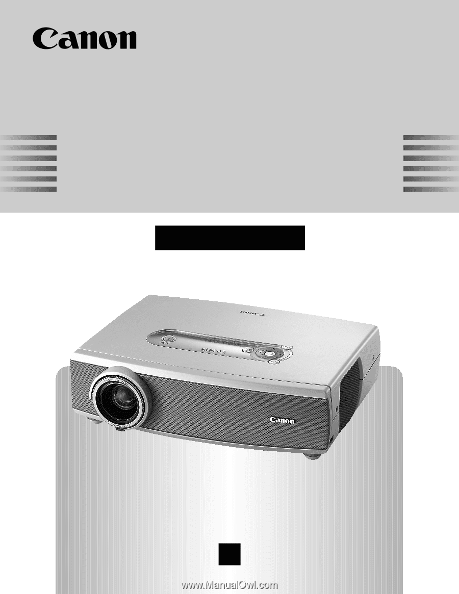
Multimedia Projector LV-7215 LV-7210 LV-5210 Owner's Manual E English - Canon LV-7215 | lv7215_7210_5210_manual.pdf - Page 2
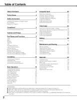
Table of Contents To the Owner Safety Instructions Installing the Projector in Proper Position Air Circulation Moving the Projector Compliance Connecting the AC Power Cord Features and Design Part Names and Functions Front Back Bottom Terminal Top Remote Control Unit Laser Pointer Function Pointer - Canon LV-7215 | lv7215_7210_5210_manual.pdf - Page 3
problem still persists, contact the dealer where you purchased the projector or the service center. CAUTION RISK OF ELECTRIC SHOCK DO NOT OPEN CAUTION : TO REDUCE THE RISK OF ELECTRIC SHOCK, DO NOT REMOVE COVER (OR BACK). NO USER-SERVICEABLE PARTS INSIDE EXCEPT LAMP REPLACEMENT. REFER SERVICING - Canon LV-7215 | lv7215_7210_5210_manual.pdf - Page 4
Follow all warnings and instructions marked on the projector. For added protection to the projector during a lightning projector exhibits a distinct change in performance-this indicates a need for service. When replacement parts are required, be sure the service technician has used replacement parts - Canon LV-7215 | lv7215_7210_5210_manual.pdf - Page 5
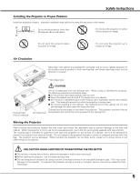
fire hazard by heat. Cooling fans are provided to cool down the projector. This projector monitors internal temperature and control the running speed of the cooling fans. Moving the Projector When moving the projector, replace the lens cover and retract the adjustable feet to prevent damage to the - Canon LV-7215 | lv7215_7210_5210_manual.pdf - Page 6
Compliance Federal Communication Commission Notice Multimedia Projector, Model : LV-7215, LV-7210, LV-5210 This device complies with Part 15 of the FCC Rules. Operation is subject to the following two conditions: (1) This device may not cause harmful interference, and (2) this device must accept - Canon LV-7215 | lv7215_7210_5210_manual.pdf - Page 7
or service station if you are not sure of the type of power being supplied. Connect the projector with all peripheral equipment before turning the projector does not match the AC outlet, contact your sales dealer. Projector side AC Outlet side For the U.S.A. and Canada Ground For Continental Europe To - Canon LV-7215 | lv7215_7210_5210_manual.pdf - Page 8
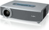
technology for portability, durability, and ease of use. This projector utilizes built-in multimedia features, a palette of 16.77 million colors, and matrix liquid crystal display (LCD) technology. N Wide Zoom Lens N User's Logo This projector is equipped with Wide Zoom Lens which is 1.6 times - Canon LV-7215 | lv7215_7210_5210_manual.pdf - Page 9
e Power Cord Connector r Infrared Remote Receiver t Zoom Lever y Projection Lens u Lens Cover (See page 54 for attaching.) i Air Intake Vent q Exhaust Vent CAUTION Hot air is exhausted from the exhaust vent. Do not put heat-sensitive objects near this side. w Top Controls and Indicators e Air Intake - Canon LV-7215 | lv7215_7210_5210_manual.pdf - Page 10
. u io q DVI-I / RGB IN-1 Connect computer output (Digital/Analog DVI-I type) or Multi Card Imager (optional) to this terminal. (p17) w SERVICE PORT This jack is used to service this projector. e AUDIO IN Connect the audio output from video equipment connected to r or i to this jack. (When the - Canon LV-7215 | lv7215_7210_5210_manual.pdf - Page 11
Part Names and Functions Top This projector has control buttons and indicators on its top. qw e r MENU SET VOL - VOL + KEY STONE LAMP REPLACE WARNING INPUT POWER t y u i q MENU button Opens or closes the On-Screen Menu. (p22) t INPUT button Selects input source. (p24, 32 ) w SET - Canon LV-7215 | lv7215_7210_5210_manual.pdf - Page 12
for wireless mouse operation. (p14) w SIGNAL EMISSION indicator The indicator lights red while the laser beam is being emitted from the Laser Light Window or a signal is being sent from the remote control to the projector. e KEYSTONE button Corrects keystone distortion. (p20, 38) r AUTO PC button - Canon LV-7215 | lv7215_7210_5210_manual.pdf - Page 13
may result. Signal Emission Indicator These caution labels are put on the remote control. Laser Light Window Pointer Function You can move Spotlight or Pointer of the projector with the remote control unit to emphasize a part of the projected image. (See "Pointer" on page 40 for changing the - Canon LV-7215 | lv7215_7210_5210_manual.pdf - Page 14
2 to Code 8). This switching function prevents remote control unit interference when operating several projectors or video equipment at the same time. (Change the remote control code for the projector first before changing that for the remote control unit. See "Remote control" on page 40.) 1 While - Canon LV-7215 | lv7215_7210_5210_manual.pdf - Page 15
the remote control to moisture, or heat. G Do not drop the remote control. G If a battery has leaked on remote control, carefully wipe case clean and install new batteries. G Risk of explosion if battery is replaced by an incorrect type. G Dispose of used batteries according to the instructions. 15 - Canon LV-7215 | lv7215_7210_5210_manual.pdf - Page 16
a room has a great influence on picture quality. It is recommended to limit ambient lighting in order to provide the best image. G The values shown are approximate and may 38) CAUTION Tilt the projector within the adjustable range in order to preserve the life of the lamp. The proper angle should be - Canon LV-7215 | lv7215_7210_5210_manual.pdf - Page 17
are not supplied with this projector.) • VGA Cable (HDB 15 pin) ✽ • DVI-VGA Cable (HDB 15 pin) • DVI-Digital Cable (for Single Link T.M.D.S.) Page 39.) SERVICE PORT S-VIDEO IN COMPUTER AUDIO IN RESET MCI RGB IN-2/ COMPONENT IN/ RGB OUT AUDIO OUT Terminals of the Projector NOTE : When - Canon LV-7215 | lv7215_7210_5210_manual.pdf - Page 18
IN-2 / COMPONENT IN/ RGB OUT S-VIDEO IN AUDIO IN VIDEO IN DVI-I/ RGB IN-1 AUDIO R IN L VIDEO IN COMPUTER AUDIO IN SERVICE PORT S-VIDEO IN COMPUTER AUDIO IN RESET MCI RGB IN-2/ COMPONENT IN/ RGB OUT AUDIO OUT Terminals of the Projector NOTE G The S-VIDEO IN jack has priority over the - Canon LV-7215 | lv7215_7210_5210_manual.pdf - Page 19
signal from Computer or Video source appears. 26 The preparation display disappears after 30 seconds. Selected Image Level and Lamp Mode Lamp mode (See page 40 for Lamp mode.) Turning Off the Projector 1 Press the POWER ON-OFF button on the top control or on the remote control unit, and a message - Canon LV-7215 | lv7215_7210_5210_manual.pdf - Page 20
right part. Keystone adjustment can be memorized. (p38) • The arrows are blue when there is no correction. • The arrows disappear at the maximum correction. • The direction of the arrow being corrected turns light blue. • If you press the KEYSTONE button on the top control or on the remote control - Canon LV-7215 | lv7215_7210_5210_manual.pdf - Page 21
Basic Operation No Show Function Press the NO SHOW button on the remote control unit to black out the image. To restore to normal, press the NO SHOW button again or press any other button. When a projected image is captured and set as "User" in the Logo item in the Setting menu (p38), the - Canon LV-7215 | lv7215_7210_5210_manual.pdf - Page 22
Basic Operation On-Screen Menu You can control and adjust this projector through the On-Screen Menu. Refer to the following pages to operate each adjustment on the On-Screen Menu. Remote Control POINT button 1 Press the MENU button to display the On-Screen Menu (Menu bar). A red frame is a - Canon LV-7215 | lv7215_7210_5210_manual.pdf - Page 23
Menu Used to adjust size of image. [Normal / True / Wide / Digital zoom +/-] (p31) Setting Menu Used to change settings of the projector or reset lamp replace counter. (p38-40) Input Menu Used to select input source either Computer or Video. (p24) PC Adjust Menu Used to adjust parameters to match - Canon LV-7215 | lv7215_7210_5210_manual.pdf - Page 24
system for protecting digital entertainment content delivered by DVI (Digital Visual Interface) from being copied. The specification of HDCP is decided and controlled by Digital Content Protection, LLC. Should the specification be changed, this projector may not display the digital content protected - Canon LV-7215 | lv7215_7210_5210_manual.pdf - Page 25
is not provided properly, manual adjustment is required. (p27, 28) - - - - There is no signal input from the connected computer. Check the connection of the computer and see if the projector is set correctly. (See "Troubleshooting" on page 45.) Mode 1 User preset adjustment in Computer Adjustment - Canon LV-7215 | lv7215_7210_5210_manual.pdf - Page 26
remote control unit. PC Adjust Menu Auto PC Adj. Automatically adjusts Fine sync, Total dots, Horizontal, and Vertical for the input signal from your computer. To store adjustment data Adjustment parameters from Auto PC Adjustment can be memorized in this projector signal is digital, a - Canon LV-7215 | lv7215_7210_5210_manual.pdf - Page 27
PC Adjustment to enable you to precisely adjust several parameters to match those signal formats. The projector has 5 independent memory areas to memorize those parameters manually adjusted. This enables you to recall the setting for a specific computer whenever you use it. 1 Press the MENU button - Canon LV-7215 | lv7215_7210_5210_manual.pdf - Page 28
SET button at the Display area icon and the Display area dialog box appears. Display area Display area V Adjusts the vertical area displayed by this projector. Press the Point Left/Right button to decrease/increase value and then press the SET button. Full screen When this function is on, SXGA - Canon LV-7215 | lv7215_7210_5210_manual.pdf - Page 29
and Custom by pressing the IMAGE button on the remote control unit. Standard Normal picture level preset on this projector. High contrast Picture adjustment improved in reproduction of image in a brighter place. The level being selected. Custom User preset image in the Image Adjust Menu (p30). 29 - Canon LV-7215 | lv7215_7210_5210_manual.pdf - Page 30
, move the red frame pointer to the Store icon and press the SET button. The message "OK?" will appear. Select [Yes] to store manual adjustment. To set this manual adjustment, select Custom by pressing the IMAGE button or through the Image Select Menu (p29). "OK?" message Move the pointer to [Yes - Canon LV-7215 | lv7215_7210_5210_manual.pdf - Page 31
LV-7215/ LV-7210, 800 x 600 for LV-5210), this projector enters "Digital zoom +" mode automatically. Wide Provides image to fit wide video projected image can be also expanded by pressing the D.ZOOM L button on the remote control. NOTE G This Screen Menu cannot be operated when "720p (HDTV)", " - Canon LV-7215 | lv7215_7210_5210_manual.pdf - Page 32
the INPUT button on the top control or the VIDEO button on the remote control unit. Before using these buttons, correct input source should be selected through menu operation as described below. INPUT button Video Computer 1 Computer 2 ✽ VIDEO button Video ✽ When Monitor out is selected at - Canon LV-7215 | lv7215_7210_5210_manual.pdf - Page 33
the INPUT button on the top control or press the COMPUTER button on the remote control unit. Before using these buttons, correct input source should be selected through menu operation as described below. INPUT button Computer 1 Computer 2 ✽ Video COMPUTER button Computer 1 Computer 2 ✽ ✽ Computer - Canon LV-7215 | lv7215_7210_5210_manual.pdf - Page 34
that you want to select and then press the SET button. Video or S-Video Auto The projector automatically detects incoming video system, and adjusts itself to optimize its performance. When Video System is PAL-M or PAL-N, select system manually. PAL / SECAM / NTSC / NTSC4.43 / PAL-M / PAL-N If the - Canon LV-7215 | lv7215_7210_5210_manual.pdf - Page 35
, Custom by pressing the IMAGE button on the remote control unit. Standard Normal picture level preset on this projector. Cinema Picture level adjusted for the picture with fine tone. Custom User preset image in the Image Adjust Menu (p36, 37). Video Input IMAGE button Standard Cinema Custom Menu - Canon LV-7215 | lv7215_7210_5210_manual.pdf - Page 36
/Right button to obtain better balance of contrast. (From 0 to 15.) Press the SET button at this icon to store the value. Progressive Interlace video signal can be displayed in a progressive picture. Off ···· Not activated. L1 ···· Select "L1" for an active picture. L2 ···· Select "L2" for a still - Canon LV-7215 | lv7215_7210_5210_manual.pdf - Page 37
manual adjustment, select Custom by pressing the IMAGE button or through the Image Select Menu (p35). Quit Closes the Image Adjust Menu. Store icon "OK?" message Move the pointer to [Yes] and then press the SET button. Screen Size Adjustment This projector image at a normal video aspect ratio of 4 - Canon LV-7215 | lv7215_7210_5210_manual.pdf - Page 38
function (above) and set it as "User". Then the captured image will be displayed when turning on the projector next time or pressing the NO SHOW button a computer can be captured up to XGA(1024 x 768). A signal from video equipment can be captured except for 720p, 1035i, and 1080i. When capturing the - Canon LV-7215 | lv7215_7210_5210_manual.pdf - Page 39
input, Component video input, or RGB Scart 21-Pin Video input, select control or remote control unit is pressed. Shutdown···· When the lamp has been fully cooled down, the power will be turned off. Off The Power management function is canceled. On start When this function is "On," the projector - Canon LV-7215 | lv7215_7210_5210_manual.pdf - Page 40
. This will cancel the top control lock. Lamp counter reset This function is used to reset the lamp replace counter. When replacing the projection lamp, reset the lamp replace counter by using this function. See page 44 for operation. Pointer Remote control Select Spotlight or Pointer with the - Canon LV-7215 | lv7215_7210_5210_manual.pdf - Page 41
the AC power cord and contact the service station for check and repair. KEY STONE OL + LAMP REPLACE WARNING POWER CAUTION DO NOT LEAVE THE PROJECTOR WITH THE AC POWER CORD CONNECTED UNDER THE ABNORMAL CONDITION. IT MAY RESULT IN FIRE OR ELECTRIC SHOCK. WARNING lights red POWER Indicator 41 - Canon LV-7215 | lv7215_7210_5210_manual.pdf - Page 42
, dry them well. Replace the air filters properly. Make sure that the air filters are fully inserted. CAUTION Do not operate the projector with the air filters removed. Dust may accumulate on the LCD panel and the projection mirror degrading picture quality. Do not put small parts into the air - Canon LV-7215 | lv7215_7210_5210_manual.pdf - Page 43
an end, the LAMP REPLACE indicator lights yellow. If this indicator lights yellow, replace the lamp with a new one promptly. Top Control This indicator lights yellow when the life of the projection lamp draws to an end. T VOL + KEY STONE LAMP REPLACE WARNING CAUTION Allow a projector to cool - Canon LV-7215 | lv7215_7210_5210_manual.pdf - Page 44
be replaced, i.e., if the LAMP REPLACE indicator lights up, replace the lamp with a new one IMMEDIATELY after the projector has cooled down. ( Follow carefully the instructions in the Lamp Replacement section of this manual. ) Continuous use of the lamp with the LAMP REPLACE indicator lighted may - Canon LV-7215 | lv7215_7210_5210_manual.pdf - Page 45
on after the POWER indicator turns red. (See "Turning Off the Projector" on page 19.) - Check the WARNING indicator. If the WARNING indicator lights red, the projector cannot be turned on. (See "Warning Indicator" on page 41.) - Check the projection lamp. (See page 43.) - Unlock Key lock for the - Canon LV-7215 | lv7215_7210_5210_manual.pdf - Page 46
mouse setting on your computer. WARNING : High voltages are used to operate this projector. Do not attempt to open the cabinet. If problems still persist after following all operating instructions, contact the dealer where you purchased the projector or the service center. Give the model number - Canon LV-7215 | lv7215_7210_5210_manual.pdf - Page 47
Condition Check the indicators for projector condition. Indicators LAMP POWER WARNING REPLACE red/green red yellow Projector Condition The projector is OFF. (The AC power cord is unplugged.) Appendix ✽ The projector is preparing for stand-by or the projection lamp is being cooled down - Canon LV-7215 | lv7215_7210_5210_manual.pdf - Page 48
Clamp Display area Display area - H Display area - V Full screen Reset Mode free Store Quit RGB( Analog ) RGB( PC Digital ) RGB( AV HDCP ) RGB Component RGB( Scart ) Auto Video S-Video Go to System (1) N/A N/A Go to System (1) Go to System (2) N/A Go to System (3) Go to System (3) Go to System - Canon LV-7215 | lv7215_7210_5210_manual.pdf - Page 49
/ Off On / Off Off User Default Yes/No On / Off On / Off Computer 2 Monitor out Eco/Normal Off Ready Shut down 1-30 Min Quit On / Off Normal mode Auto mode Silent mode Spotlight Pointer Code 1 Code 2 Code 3 Code 4 Code 5 Code 6 Code 7 Code 8 Quit Off Projector Remote Control Quit Yes / No Yes / No - Canon LV-7215 | lv7215_7210_5210_manual.pdf - Page 50
and less than 100/MHz of Dot Clock. These modes are not available on LV-5210. ON-SCREEN DISPLAY RESOLUTION VGA 1 640 x 480 VGA 2 720 x 400 ) 60.00 (Interlace) 50.00 (Interlace) When an input signal is digital from DVI terminal, refer to the chart below. ON-SCREEN DISPLAY RESOLUTION D- - Canon LV-7215 | lv7215_7210_5210_manual.pdf - Page 51
with manual zoom and focus Throw Distance Projector Lamp 3.3' ~ 25.3' (1.0 m ~ 7.7 m) 200W Video Input Jacks Audio Input Jacks RCA Type x 1 (Video) and Mini DIN 4 pin x 1 (S-Video) RCA Type x 2 DVI-I /RGB IN-1 Terminal RGB IN-2 / COMPONENT IN / RGB OUT Terminal DVI-I Terminal (Digital/Analog - Canon LV-7215 | lv7215_7210_5210_manual.pdf - Page 52
(Green) 8 Ground (Blue) 9 +5V Power 10 Ground (Vert.sync.) 11 Sense 0 12 DDC Data 13 Horiz. sync. 14 Vert. sync. 15 DDC Clock DVI-I TERMINAL (DIGITAL/ANALOG) Terminal : DVI-I Pin Configuration C1 C2 12345678 9 10 11 12 13 14 15 16 17 18 19 20 21 22 23 24 C3 C4 - Canon LV-7215 | lv7215_7210_5210_manual.pdf - Page 53
listed below are optionally supplied. When ordering those parts, give the name and Type No. to the sales dealer. G MAC Adapter G DVI Cable G COMPONENT-VGA Cable G SCART-VGA Cable (This cable is used for RGB Scart 21-Pin Video output of video equipment.) G Multi Card Imager G Compact Flash Card - Canon LV-7215 | lv7215_7210_5210_manual.pdf - Page 54
the lens cover. 1 Secure the string for the lens cover through a hole of the lens cover. 2 Turn the projector upside down and secure the string for lens cover to a hole on the bottom of the projector with a screw. Hole String for the lens cover Secure it to the hole with a screw. 54 - Canon LV-7215 | lv7215_7210_5210_manual.pdf - Page 55
55 - Canon LV-7215 | lv7215_7210_5210_manual.pdf - Page 56
Hong Kong Club Building, 3A Chater Road, Central, Hong Kong CANON SINGPORE PTE. LTD. 79 Anson Road #09-01/06, Singapore 079906 CANON AUSTRALIA PTY. LTD. 1 Thomas Holt Drive, North Ryde, Sydney, N.S.W.2113, Australia CANON NEW ZEALAND LTD. Akoranga Business Park, Akoranga Drive, Northcote, Auckland
-
 1
1 -
 2
2 -
 3
3 -
 4
4 -
 5
5 -
 6
6 -
 7
7 -
8
-
9
-
10
-
11
-
12
-
13
-
14
-
15
-
16
-
17
-
18
-
19
-
20
-
21
-
22
-
23
-
24
-
25
-
26
-
27
-
28
-
29
-
30
-
31
-
32
-
33
-
34
-
35
-
36
-
37
-
38
-
39
-
40
-
41
-
42
-
43
-
44
-
45
-
46
-
47
-
48
-
49
-
50
-
51
-
52
-
53
-
54
-
55
-
56
 |
 |
E
English
Multimedia Projector
Owner’s Manual
LV-7215 LV-7210 LV-5210