Cisco 1760-V3PN Hardware Installation Guide - Page 107
Connecting an ADSL Card to the Wall Jack
 |
UPC - 746320802862
View all Cisco 1760-V3PN manuals
Add to My Manuals
Save this manual to your list of manuals |
Page 107 highlights
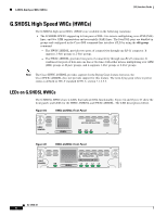
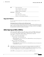
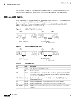
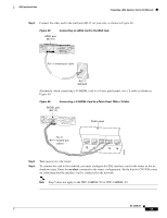
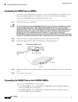
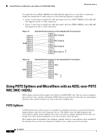
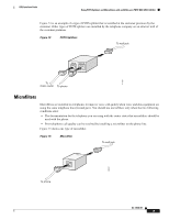
DSL Interface Cards Connecting a DSL Interface Card to the Network Step 3 Connect the other end to the wall jack (RJ-11) at your site, as shown in Figure 68. Figure 68 Connecting an ADSL Card to the Wall Jack ADSL port (RJ-11) ADSL SEE MANUAL BEFORE INSTALLATION CD LP OK RJ-11 twisted-pair cable 37701 RJ-11 wall jack Alternately, when connecting a G.SHDSL card to a 4-wire patch panel, use a Y-cable as shown in Figure 69. Figure 69 Connecting a G.SHDSL Card to a Patch Panel With a Y-Cable SHDSL port (RJ-11) WIC 1SHDSL V2 SHDSL SEE MANUAL BEFORE INSTALLATION CD LP OK Patch panel RJ-11 twisted-pair cables 10 11 12 13 14 103235 Step 4 Step 5 Turn on power to the router. To connect the card to the network, you must configure the DSL interface card in the router to the no shutdown state. Enter the no shut command in the router configuration. Verify that the CD LED comes on, indicating that the interface card is connected to the network. Note Step 5 does not apply to the WIC-1SHDSL-V2 or WIC-1SHDSL-V3. OL-12846-01 11
-
 1
1 -
2
-
3
-
4
-
5
-
6
-
7
-
8
-
9
-
10
-
11
-
12
-
13
-
14
-
15
-
16
-
17
-
18
-
19
-
20
-
21
-
22
-
23
-
24
-
25
-
26
-
27
-
28
-
29
-
30
-
31
-
32
-
33
-
34
-
35
-
36
-
37
-
38
-
39
-
40
-
41
-
42
-
43
-
44
-
45
-
46
-
47
-
48
-
49
-
50
-
51
-
52
-
53
-
54
-
55
-
56
-
57
-
58
-
59
-
60
-
61
-
62
-
63
-
64
-
65
-
66
-
67
-
68
-
69
-
70
-
71
-
72
-
73
-
74
-
75
-
76
-
77
-
78
-
79
-
80
-
81
-
82
-
83
-
84
-
85
-
86
-
87
-
88
-
89
-
90
-
91
-
92
-
93
-
94
-
95
-
96
-
97
-
98
-
99
-
100
-
101
-
 102
102 -
 103
103 -
 104
104 -
 105
105 -
 106
106 -
 107
107 -
 108
108 -
 109
109 -
 110
110 -
 111
111 -
 112
112 -
113
-
114
-
115
-
116
-
117
-
118
-
119
-
120
-
121
-
122
-
123
-
124
-
125
-
126
-
127
-
128
-
129
-
130
-
131
-
132
-
133
-
134
-
135
-
136
-
137
-
138
-
139
-
140
-
141
-
142
-
143
-
144
-
145
-
146
-
147
-
148
-
149
-
150
-
151
-
152
-
153
-
154
-
155
-
156
-
157
-
158
-
159
-
160
-
161
-
162
-
163
-
164
-
165
-
166
-
167
-
168
-
169
-
170
-
171
-
172
-
173
-
174
-
175
-
176
-
177
-
178
-
179
-
180
-
181
-
182
-
183
-
184
-
185
-
186
-
187
-
188
-
189
-
190
-
191
-
192
-
193
-
194
-
195
-
196
-
197
-
198
-
199
-
200
-
201
-
202
-
203
-
204
-
205
-
206
-
207
-
208
-
209
-
210
-
211
-
212
-
213
-
214
-
215
-
216
 |
 |
