Cisco 3725 Hardware Installation Guide - Page 59
DC Wiring Requirements for Cisco 3725 Routers, DC Power, Source, DC Input, Wire Size, Safety Ground
 |
UPC - 746320810911
View all Cisco 3725 manuals
Add to My Manuals
Save this manual to your list of manuals |
Page 59 highlights
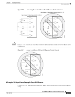
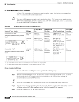
Chapter 3 Installing the Router Power Connections DC Wiring Requirements for Cisco 3725 Routers Warning This product relies on the building's installation for short-circuit (overcurrent) protection. Ensure that the protective device is rated not greater than: 15A, 60VDC. Statement 1005 Caution Dual sources with opposite-polarity grounding damage equipment. A Cisco 3725 router with a DC-input power supply requires copper wire and crimp-type terminals for the power connections. Table 3-1 summarizes the wiring requirements. Table 3-1 DC Wiring Requirements for Cisco 3725 Routers DC Power Source DC Input DC Input Wire Size Nominal 24/48 24-36 VDC, 9 A, positive or VDC1 negative, single source or dual sources AWG 18 (1.0 mm2) 36-60 VDC, 4 A, positive or negative, single source or dual sources AWG 18 (1.0 mm2) 1. The input voltage tolerance limits for DC power are 18 and 72 VDC. Safety Ground Wire Size Wire Terminal (Lug) AWG 14 (2.0 mm2) Molex part number 19193-0017, or equivalent AWG 14 (2.0 mm2) Molex part number 19193-0017, or equivalent Overcurrent Protection 15 A maximum 15 A maximum Wiring Procedure for Cisco 3725 Routers To connect a Cisco 3725 router to a DC power source, perform the following steps: Step 1 Remove power from the DC circuit. To ensure that power is removed from the DC circuit, locate the circuit breaker for the DC circuit, switch the circuit breaker to the OFF position, and tape the circuit-breaker switch in the OFF position. Tip Secure all power cabling when installing this unit to avoid disturbing field-wiring connections. Step 2 Step 3 Strip the wires to the appropriate length for the terminals. The strip length is 1/8 to 3/16 inch (3 to 5 mm) for Molex number 19193-0009 and for AMP number 324159-0 terminals. Crimp the terminals to the power input and safety ground wires. Warning When stranded wiring is required, use approved wiring terminations, such as closed-loop or spade-type with upturned lugs. These terminations should be the appropriate size for the wires and should clamp both the insulation and conductor. Statement 1002 Step 4 Step 5 Remove the plastic cover from the terminal block. Save it for reinstallation after you finish wiring. Connect the DC power input wires to the terminal block as shown in Figure 3-16. To avoid interference with the on/off switch, organize the wires downward from the terminal block. OL-2180-08 Cisco 3700 Series Routers Hardware Installation Guide 3-13
-
 1
1 -
2
-
3
-
4
-
5
-
6
-
7
-
8
-
9
-
10
-
11
-
12
-
13
-
14
-
15
-
16
-
17
-
18
-
19
-
20
-
21
-
22
-
23
-
24
-
25
-
26
-
27
-
28
-
29
-
30
-
31
-
32
-
33
-
34
-
35
-
36
-
37
-
38
-
39
-
40
-
41
-
42
-
43
-
44
-
45
-
46
-
47
-
48
-
49
-
50
-
51
-
52
-
53
-
 54
54 -
 55
55 -
 56
56 -
 57
57 -
 58
58 -
 59
59 -
 60
60 -
 61
61 -
 62
62 -
 63
63 -
 64
64 -
65
-
66
-
67
-
68
-
69
-
70
-
71
-
72
-
73
-
74
-
75
-
76
-
77
-
78
-
79
-
80
-
81
-
82
-
83
-
84
-
85
-
86
-
87
-
88
-
89
-
90
-
91
-
92
-
93
-
94
-
95
-
96
-
97
-
98
-
99
-
100
-
101
-
102
-
103
-
104
-
105
-
106
-
107
-
108
-
109
-
110
-
111
-
112
-
113
-
114
 |
 |
