Cisco 5505 Installation Guide - Page 12
Rear Panel Components - power supply
 |
UPC - 882658082252
View all Cisco 5505 manuals
Add to My Manuals
Save this manual to your list of manuals |
Page 12 highlights
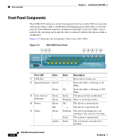
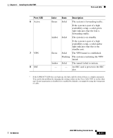
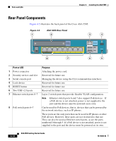
Ports and LEDs Chapter 4 Installing the ASA 5505 153383 Rear Panel Components Figure 4-5 illustrates the back panel of the Cisco ASA 5505. Figure 4-5 1 ASA 5505 Rear Panel 2 3 4 Security Services Card Slot power 48VDC 7 POWER over ETHERNET 6 5 4 3 2 1 0 8 7 Console 2 RESET 1 6 5 Port or LED 1 Power connector 2 Security service card slot 3 Serial console port 4 Lock device 5 RESET button 6 Two USB v2.0 ports 7 Ethernet switch ports 0-7 8 PoE switch ports 6-7 Purpose Attaching the power cord. Reserved for future use. Managing the device using the CLI (command-line interface). Reserved for future use. Reserved for future use. Reserved for future use. Layer 2 switch ports that provide flexible VLAN configuration. Note Ethernet switch ports 6 and 7 also support PoE devices. If a PoE device is not attached, power is not supplied to the port and the device must be powered on its own. Can be used for PoE devices, that is, devices that can be powered by the network interface, such as IP phones. These ports are the only ports that can be used for IP phones or other PoE devices. However, these ports are not restricted to that use. They can also be used as Ethernet switch ports, as are the ports numbered 0 through 5. If a PoE device is not attached, power is not supplied to the port and the device must be powered on its own. 4-12 ASA 5505 Getting Started Guide 78-18003-02
-
 1
1 -
2
-
3
-
4
-
5
-
6
-
 7
7 -
 8
8 -
 9
9 -
 10
10 -
 11
11 -
 12
12 -
 13
13 -
 14
14
 |
 |
