Cisco 5505 Installation Guide - Page 9
Installing a Cable Lock, Ports and LEDs - manufacturer
 |
UPC - 882658082252
View all Cisco 5505 manuals
Add to My Manuals
Save this manual to your list of manuals |
Page 9 highlights
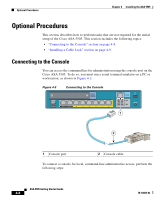
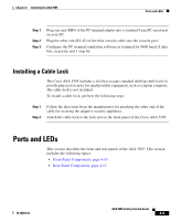
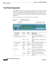
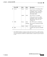
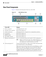
Chapter 4 Installing the ASA 5505 Ports and LEDs Step 1 Step 2 Step 3 Plug one end (DB9) of the PC terminal adapter into a standard 9-pin PC serial port on your PC. Plug the other end (RJ-45) of the blue console cable into the console port. Configure the PC terminal emulation software or terminal for 9600 baud, 8 data bits, no parity, and 1 stop bit. Installing a Cable Lock The Cisco ASA 5505 includes a slot that accepts standard desktop cable locks to provide physical security for small portable equipment, such as a laptop computer. The cable lock is not included. To install a cable lock, perform the following steps: Step 1 Step 2 Follow the directions from the manufacturer for attaching the other end of the cable for securing the adaptive security appliance. Attach the cable lock to the lock slot on the back panel of the Cisco ASA 5505. Ports and LEDs This section describes the front and rear panels of the ASA 5505. This section includes the following topics: • Front Panel Components, page 4-10 • Rear Panel Components, page 4-12 78-18003-02 ASA 5505 Getting Started Guide 4-9
-
 1
1 -
2
-
3
-
 4
4 -
 5
5 -
 6
6 -
 7
7 -
 8
8 -
 9
9 -
 10
10 -
 11
11 -
 12
12 -
 13
13 -
 14
14
 |
 |