Cisco AIR-AP1010 Quick Start Guide - Page 16
Configuration Steps for an AP prior to installation, LWAPP Layer 3 Mode - power injector
 |
UPC - 882658154027
View all Cisco AIR-AP1010 manuals
Add to My Manuals
Save this manual to your list of manuals |
Page 16 highlights
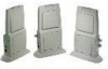
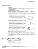
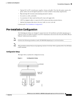
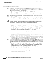
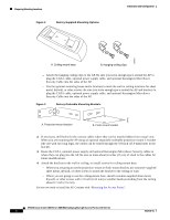
Pre-Installation Configuration Installation and Configuration Configuration Steps for an AP prior to installation Step 1 Step 2 Step 3 Configure the Cisco Wireless LAN Controller in LWAPP Layer 3 Mode and be sure its DS Port is connected to the network. Use CLI, Web User Interface or Cisco WCS procedures as described in the appropriate Cisco Wireless LAN Controller Guide. a. Be sure AP ports are available through the Cisco Wireless LAN Controller Management/AP-Manager Interface. b. Set the Cisco Wireless LAN Controller as the Master so that new AP always associate with it. Take the AP out of the box and plug it into the same subnet as the Cisco Wireless LAN Controller. Apply power to the AP: a. Use 802.3af-compatible PoE from an orderable inline power injector. If you do not have PoE available, use an orderable AC-to-48 VDC External Power Supply plugged into the side of the AP. Note These APs support 802.3af Power over Ethernet (PoE). These access points do not support Cisco prestandard PoE. Please use Cisco 802.3af capable PoE switches or power injectors. Step 4 b. After you power up the AP, the RED Alarm LED comes on for about 15-20 seconds and then all the LEDs blink sequentially back and forth, indicating that the AP is trying to find a Cisco Wireless LAN Controller to associate with. This can continue for up to five minutes. If the AP remains in this mode for more than five minutes, the AP is unable to find the Master Cisco Wireless LAN Controller. Check the connection between the AP and the Cisco Wireless LAN Controller and be sure the AP and the Cisco Wireless LAN Controller are on the same subnet. c. If the power light does not come on, check the power (it can be powered either with PoE or from an orderable AP External Power Supply. d. Be sure that a DHCP server is configured in the Cisco Wireless LAN Controller for both the Management Interface and AP-Manager Interface using the CLI, Web User Interface, or Cisco WCS interface, and that the DHCP server is operating correctly. e. After the AP finds the Cisco Wireless LAN Controller, it attempts to download the new Operating System code if the AP code version differs from the Cisco Wireless LAN Controller code version. While this is happening, the LEDs on the top of the AP blink simultaneously. After the Operating System code download is successful, the AP reboots. The GREEN LED turns on and the two YELLOW LEDs indicate the states of the 802.11a and 802.11b/g networks. If any part of the network is disabled in the Cisco Wireless LAN Controller, the corresponding YELLOW LED remains off. • Note that the Red LED can light for about 10-20 seconds when the AP reboots. If the RED LED comes on AND STAYS ON for more than a minute, disconnect the Cisco Aironet 1000 Series lightweight access point and call Cisco Technical Assistance Center (TAC). • From the CLI, Web User Interface or Cisco WCS interface, configure the AP with its Primary, Secondary, and Tertiary Cisco Wireless LAN Controller names. • If required, use the CLI, Web User Interface or Cisco WCS interface to customize the AP-specific 802.11a, 802.11b and 802.11g network settings. Once again, the two YELLOW LEDs indicate the states of the 802.11a and 802.11b/g networks. If any part of the network is disabled, the corresponding YELLOW LED remains off. AP1010 Cisco Aironet 1000 Series IEEE 802.11a/b/g Lightweight Access Points with Internal 4 7817146-01
-
 1
1 -
2
-
3
-
4
-
5
-
6
-
7
-
8
-
9
-
10
-
 11
11 -
 12
12 -
 13
13 -
 14
14 -
 15
15 -
 16
16 -
 17
17 -
 18
18 -
 19
19 -
 20
20 -
 21
21 -
22
-
23
-
24
-
25
-
26
-
27
-
28
-
29
-
30
-
31
-
32
-
33
-
34
-
35
-
36
 |
 |