Cisco AIR-AP1010 Quick Start Guide - Page 24
Attaching the Mounting Screws and Spring Washers to the AP
 |
UPC - 882658154027
View all Cisco AIR-AP1010 manuals
Add to My Manuals
Save this manual to your list of manuals |
Page 24 highlights
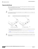
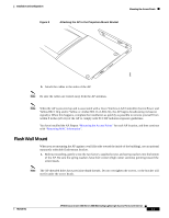
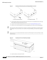
135669 135667 Mounting the Access Points Installation and Configuration Figure 9 Attaching the Mounting Screws and Spring Washers to the AP A. Screws and spring washers B. Completed assembly 2. Copy the MAC address(es) from the label(s) on the AP onto the corresponding location on the map. MAC addresses have the format 00xxxxxxxxxx. 3. You have already attached the flush-mount bracket to the wall in "Preparing Mounting Locations". 4. Slide the screws into the keyhole slots on the mounting bracket as shown in the following figure. Note Be sure the side of the AP with the door is facing away from the wall (flat Side A toward the inside of the building). This ensures that the correct antenna is facing the building, and makes future upgrades easier. Note If the screws do not securely hold the bracket, remove the AP and adjust the screws until they securely hold the bracket. Figure 10 Attaching the AP to the Flush-Mount Bracket 5. Attach the cables to the sides of the AP. AP1010 Cisco Aironet 1000 Series IEEE 802.11a/b/g Lightweight Access Points with Internal 12 7817146-01
-
 1
1 -
2
-
3
-
4
-
5
-
6
-
7
-
8
-
9
-
10
-
11
-
12
-
13
-
14
-
15
-
16
-
17
-
18
-
 19
19 -
 20
20 -
 21
21 -
 22
22 -
 23
23 -
 24
24 -
 25
25 -
 26
26 -
 27
27 -
 28
28 -
 29
29 -
30
-
31
-
32
-
33
-
34
-
35
-
36
 |
 |
