Coby TFTV3227 Instruction Manual - Page 10
Wall Mounting - Attach the TV case to the wall - z tv
 |
UPC - 716829993279
View all Coby TFTV3227 manuals
Add to My Manuals
Save this manual to your list of manuals |
Page 10 highlights
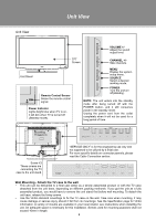
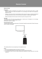
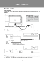
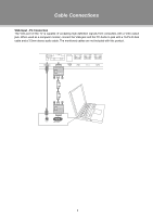
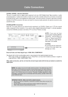
Unit View Unit View VOLUME +/Adjust the sound output level. TFT Screen CHANNEL +/Skip channels. Unit Stand Remote Control Senser Sense the remote control signal. Power Indicator Lights bright blue when TV is on, it will dim when TV is turned off (Standby mode). MENU Display the system setup menu. SOURCE Select a desired working mode. POWER Turn the unit on/ off(standby). NOTE: The unit enters into the standby mode after being turned off with the POWER button, and it still consumes power in the standby mode. Unplug the power cord from the outlet completely when it will not be used for a long period of time. Mounting Thread x 4. Screw X3 These screws are connecting the TV case to the unit stand. "SERVICE ONLY" is for the engineering use only and not supposed to be utilized by a finial user. For more specific details on connector pannels, please read the Cable Connection section Wall Mounting - Attach the TV case to the wall •• This unit can be deliveried to a final user either as a wholly assembled product or with the TV case detached from the unit base, depending on different packing methords. If you got the unit as a fully assembled product, you would have to remove the unit stand first before wall mounting, To detach the unit base, release the fixing screws. •• Use the VESA standard mountings to fix the TV case on the wall. Take care when mounting, it may cause damage or serious injury should it fall from its mountings. See the Specification page for VESA informaiton. A variety of mounts are available in your local retailer, see instructions when installing the unit. An adequate space is necessary for this installation. Screws used for mounting purposes shall not exceed 10mm in length. 3
-
 1
1 -
2
-
3
-
4
-
 5
5 -
 6
6 -
 7
7 -
 8
8 -
 9
9 -
 10
10 -
 11
11 -
 12
12 -
 13
13 -
 14
14 -
 15
15 -
16
-
17
-
18
-
19
-
20
-
21
-
22
-
23
-
24
-
25
 |
 |
