Compaq 210189-001 Compaq P710/P910/P1210 Color Monitor User's Guide - Page 9
Installation And, Connection
 |
UPC - 720591500153
View all Compaq 210189-001 manuals
Add to My Manuals
Save this manual to your list of manuals |
Page 9 highlights
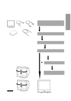
ENGLISH 3 INSTALLATION AND CONNECTION 17" and 19" Models On the back of the monitor two kinds of plug-in connections are provided: AC power connector for the AC input, DB915P connector for video signal input. AC Power Connection One end of the AC power cord is connected to the AC power connector on the back of the monitor. The other end is plugged into a properly grounded three-prong AC outlet. The monitor's auto-sensing power supply can automatically detect 100-120V AC or 220-240V AC and 50 or 60Hz. Signal Cable Connection The attached signal cable provides a DB9-15P connector for the VGA compatible analog RGB outputs on your computer. The figure below shows the included signal cable connection to the Video Graphics Array (VGA) port. 1. Power off, both the monitor and the computer. 2. Connect one end of the signal cable to the DB9-15P connector on the VGA controller card. 3. Connect the other end of the signal cable to the DB9- 15P receptacle on the back of the monitor. 4. Power on the monitor, then the computer. 5. After using the system, power off the monitor, then the computer. D-sub D-sub Computer VGA Compatible System DB9-15P Power Cord Cable SC-B104 CAUTION The socket-outlet shall be installed near the equipment and shall be easily accessible. During servicing, disconnect the plug from the socket-outlet. 22" Model On the back of the monitor three kinds of plug-in connections are provided: AC power connector for the AC input, and two DB9-15P connectors for video signal input and USB ports for USB communication. AC Power Connection One end of the AC power cord is connected to the AC power connector on the back of the monitor. The other end is plugged into a properly grounded three-prong AC outlet. The monitor's auto-sensing power supply can automatically detect 100-120V AC or 220-240V AC and 50 or 60Hz. Signal Cable Connection The DB9-15P(VGA) connector is provided for compatible analog RGB outputs from your computer. Connecting to VGA Compatible System The figure below shows the SC-B104 cable connection to the Video Graphics Array (VGA) port in any VGA compatible system. 1. Power off, both the monitor and the computer. 2. Connect the one end of the SC-B104 cable to the DB9- 15P connector on the VGA controller card. 3. Connect the other end of the SC-B104 cable to the DB9-15P receptacle on the back of the monitor. 4. Power on the monitor, then the computer. 5. After using the system, power off the monitor, then the computer. 12 3 SIGNAL-A SIGNAL-B SIGNAL-A SIGNAL-B Computer VGA Compatible System Power Cord Cable SC-B104 CAUTION The socket-outlet shall be installed near the equipment and shall be easily accessible. During servicing, disconnect the plug from the socket-outlet. Connecting to two computers (22" Model) The figure below shows the connection to two computers. D-SUB D-SUB B SIGNAL-A SIGNAL-B Computer B VGA Computer A Cable SC-B104 - 1 -
-
 1
1 -
2
-
3
-
 4
4 -
 5
5 -
 6
6 -
 7
7 -
 8
8 -
 9
9 -
 10
10 -
 11
11 -
 12
12 -
 13
13 -
 14
14 -
15
-
16
-
17
-
18
-
19
-
20
-
21
-
22
-
23
-
24
-
25
-
26
-
27
-
28
-
29
 |
 |
