Compaq Armada 110 Compaq Armada 110 and Compaq Evo N110 Maintenance and Servic - Page 144
Table C-3, M2.5 × 7 Screw, Screw Listing, Maintenance and Service Guide, Hardware Guide
 |
View all Compaq Armada 110 manuals
Add to My Manuals
Save this manual to your list of manuals |
Page 144 highlights
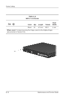
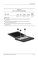
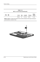
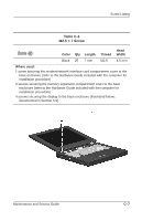
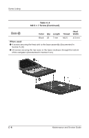
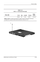
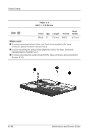
Screw Listing Table C-3 M2.5 × 7 Screw Head Color Qty Length Thread Width Black 25 7 mm M2.5 4.5 mm Where used: 1 screw securing the modem/network interface card compartment cover to the base enclosure (refer to the Hardware Guide included with the computer for installation procedure) 2 screws securing the memory expansion compartment cover to the base enclosure (refer to the Hardware Guide included with the computer for installation procedure) 4 screws securing the display to the base enclosure (illustrated below; documented in Section 5.9) Maintenance and Service Guide C-7
-
 1
1 -
2
-
3
-
4
-
5
-
6
-
7
-
8
-
9
-
10
-
11
-
12
-
13
-
14
-
15
-
16
-
17
-
18
-
19
-
20
-
21
-
22
-
23
-
24
-
25
-
26
-
27
-
28
-
29
-
30
-
31
-
32
-
33
-
34
-
35
-
36
-
37
-
38
-
39
-
40
-
41
-
42
-
43
-
44
-
45
-
46
-
47
-
48
-
49
-
50
-
51
-
52
-
53
-
54
-
55
-
56
-
57
-
58
-
59
-
60
-
61
-
62
-
63
-
64
-
65
-
66
-
67
-
68
-
69
-
70
-
71
-
72
-
73
-
74
-
75
-
76
-
77
-
78
-
79
-
80
-
81
-
82
-
83
-
84
-
85
-
86
-
87
-
88
-
89
-
90
-
91
-
92
-
93
-
94
-
95
-
96
-
97
-
98
-
99
-
100
-
101
-
102
-
103
-
104
-
105
-
106
-
107
-
108
-
109
-
110
-
111
-
112
-
113
-
114
-
115
-
116
-
117
-
118
-
119
-
120
-
121
-
122
-
123
-
124
-
125
-
126
-
127
-
128
-
129
-
130
-
131
-
132
-
133
-
134
-
135
-
136
-
137
-
138
-
 139
139 -
 140
140 -
 141
141 -
 142
142 -
 143
143 -
 144
144 -
 145
145 -
 146
146 -
 147
147 -
 148
148 -
 149
149 -
150
-
151
-
152
-
153
 |
 |

Screw Listing
Maintenance and Service Guide
C
–
7
Table C-3
M2.5 × 7 Screw
Color
Qty
Length
Thread
Head
Width
Black
25
7 mm
M2.5
4.5 mm
Where used:
1 screw securing the modem/network interface card compartment cover to the
base enclosure (refer to the
Hardware Guide
included with the computer for
installation procedure)
2 screws securing the memory expansion compartment cover to the base
enclosure (refer to the
Hardware Guide
included with the computer for
installation procedure)
4 screws securing the display to the base enclosure (illustrated below;
documented in Section 5.9)