Compaq Armada m700 Compaq Armada M700 Series of Personal Computers Maintenance - Page 140
Power-On Self-Test POST, Info Messenger
 |
View all Compaq Armada m700 manuals
Add to My Manuals
Save this manual to your list of manuals |
Page 140 highlights
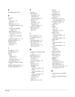
P packaging precautions, 4-3 parallel connector illustrated, 1-13 pinout, A-2 password clearing, 2-3 PC Card, 5-14 inserting, 5-16 removing, 5-15 slots, illustrated, 1-15 pick button, illustrated, 1-19 plastic parts, handling, 4-1 Plastics Kit components illustrated, 3-8 components, illustrated, 3-2 spare part number, 3-3, 3-9 pointing device caps spare part number, 3-12 ports, default settings, 2-12 POST (Power-On Self-Test), 2-3 error messages, 2-4 power cord spare part number, 3-7 cord set country-specific requirements, 0-2 general requirements, 0-1 requirements, B-1, 0-1 default settings, 2-12 equipment, overview, 1-11 managing, 1-9 switch, illustrated, 1-17 power connector, illustrated, 1-13 Power-On Self-Test (POST), 2-3 Q QuickBoot, 2-10 R RAM board, illustrated, 3-10 real time clock (RTC) battery illustrated, 3-10 removal, 5-19 RJ-11 jack pinout, A-1 RJ-11 jack, illustrated, 1-15 RJ-45 jack, illustrated, 1-15 RTC (real time clock) battery illustrated, 3-10 removal, 5-19 S scroll button, illustrated, 1-19 scroll lock light, illustrated, 1-17 Security Management, 1-8 security, default settings, 2-12 serial connector illustrated, 1-13 pinout, A-1 serial number, viii serial number, location, 3-1, 5-1 service considerations, 4-1 setup, 2-7 Sleep button, 1-17 software Info Messenger, 2-13 updating, 2-13 speakers, illustrated, 1-17 specifications battery pack, 6-8 CD-ROM drive, 6-5 diskette drive, 6-4 display, 6-2 DMA, 6-8 DVD-ROM drive, 6-6 I/O addresses, 6-10 interrupts, 6-9 LS-120 SuperDisc drive, 6-7 memory map, 6-12 Standby, 1-17 stereo line-in jack, pinout, A-2 stereo speaker jack illustrated, 1-12 pinout, A-2 Suspend button, illustrated, 1-17 switch cover illustrated, 3-2, 3-8 removal, 5-24 system DMA, 6-8 I/O address, 6-10 IDs, 2-9 interrupts, 6-9 memory map, 6-12 ROM updates, 2-13 system board illustrated, 3-2 overview, 1-21 removal, 5-36 system on light, illustrated, 1-12 T technical notes, vii tools required for service, 4-1 top cover illustrated, 3-2 removal, 5-29 spare part number, 3-3 touch button illustrated, 3-2 spare part number, 3-3 TouchPad illustrated, 1-20, 3-2 spare part number, 3-3 TouchPad button, illustrated, 1-20 TouchPad button, illustrated, 1-20 transporting precautions, 4-3 troubleshooting checklist, 2-14 preliminary steps, 2-2 without diagnostics, 2-13 Index I-3
-
 1
1 -
2
-
3
-
4
-
5
-
6
-
7
-
8
-
9
-
10
-
11
-
12
-
13
-
14
-
15
-
16
-
17
-
18
-
19
-
20
-
21
-
22
-
23
-
24
-
25
-
26
-
27
-
28
-
29
-
30
-
31
-
32
-
33
-
34
-
35
-
36
-
37
-
38
-
39
-
40
-
41
-
42
-
43
-
44
-
45
-
46
-
47
-
48
-
49
-
50
-
51
-
52
-
53
-
54
-
55
-
56
-
57
-
58
-
59
-
60
-
61
-
62
-
63
-
64
-
65
-
66
-
67
-
68
-
69
-
70
-
71
-
72
-
73
-
74
-
75
-
76
-
77
-
78
-
79
-
80
-
81
-
82
-
83
-
84
-
85
-
86
-
87
-
88
-
89
-
90
-
91
-
92
-
93
-
94
-
95
-
96
-
97
-
98
-
99
-
100
-
101
-
102
-
103
-
104
-
105
-
106
-
107
-
108
-
109
-
110
-
111
-
112
-
113
-
114
-
115
-
116
-
117
-
118
-
119
-
120
-
121
-
122
-
123
-
124
-
125
-
126
-
127
-
128
-
129
-
130
-
131
-
132
-
133
-
134
-
 135
135 -
 136
136 -
 137
137 -
 138
138 -
 139
139 -
 140
140 -
 141
141
 |
 |
