Compaq DC7600 Hardware Reference Guide - dc7600 CMT - Page 42
Computer, Setup F10 Utility, Guide, Documentation and Diagnostics
 |
UPC - 882780682009
View all Compaq DC7600 manuals
Add to My Manuals
Save this manual to your list of manuals |
Page 42 highlights
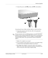
Hardware Upgrades ✎ If you are installing a third optional drive in the bottom 5.25-inch drive bay, you must also install an expansion card with an IDE controller and data cable (not supplied) because the secondary IDE controller supports only two drives. ✎ If you are installing a third optional drive, you may need to remove the strap that bundles the extra power connectors. 6. Connect the power and signal cables to the rear of the drive. Connecting the Drive Cables 7. Remove the appropriate bezel blank from the subpanel inside the front bezel. See the "Removing Bezel Blanks" section for more information. 8. Replace the computer access panel and front bezel. 9. If you normally lock the Smart Cover Lock, use Computer Setup to relock the lock and enable the Smart Cover Sensor. 10. Reconfigure the computer, if necessary. Refer to the Computer Setup (F10) Utility Guide on the Documentation and Diagnostics CD for instructions about using Computer Setup. 2-26 www.hp.com Hardware Reference Guide
-
 1
1 -
2
-
3
-
4
-
5
-
6
-
7
-
8
-
9
-
10
-
11
-
12
-
13
-
14
-
15
-
16
-
17
-
18
-
19
-
20
-
21
-
22
-
23
-
24
-
25
-
26
-
27
-
28
-
29
-
30
-
31
-
32
-
33
-
34
-
35
-
36
-
 37
37 -
 38
38 -
 39
39 -
 40
40 -
 41
41 -
 42
42 -
 43
43 -
 44
44 -
 45
45 -
 46
46 -
 47
47 -
48
-
49
-
50
-
51
-
52
-
53
-
54
-
55
-
56
-
57
-
58
-
59
-
60
-
61
-
62
-
63
-
64
-
65
-
66
-
67
-
68
-
69
 |
 |
