Compaq Presario 1800 Presario Selct 1800 Series Maintenance and Service Guide - Page 56
Return to Removal &, Replacement Procedures
 |
View all Compaq Presario 1800 manuals
Add to My Manuals
Save this manual to your list of manuals |
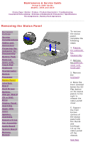
Page 56 highlights
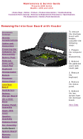
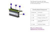
The following illustration and table indicates the locations of the connectors on the interface board. Interface Board Components Designator Connector 1. JP1 Backlight Switch 2. JP3 Display Interface ZIF 3. JP4 Inverter/Backlight LIF Connector 4. None Interface Header Return to Removal & Replacement Procedures
-
 1
1 -
2
-
3
-
4
-
5
-
6
-
7
-
8
-
9
-
10
-
11
-
12
-
13
-
14
-
15
-
16
-
17
-
18
-
19
-
20
-
21
-
22
-
23
-
24
-
25
-
26
-
27
-
28
-
29
-
30
-
31
-
32
-
33
-
34
-
35
-
36
-
37
-
38
-
39
-
40
-
41
-
42
-
43
-
44
-
45
-
46
-
47
-
48
-
49
-
50
-
 51
51 -
 52
52 -
 53
53 -
 54
54 -
 55
55 -
 56
56 -
 57
57 -
 58
58 -
 59
59 -
 60
60 -
 61
61 -
62
-
63
-
64
-
65
-
66
-
67
-
68
-
69
-
70
-
71
-
72
-
73
-
74
-
75
-
76
-
77
 |
 |
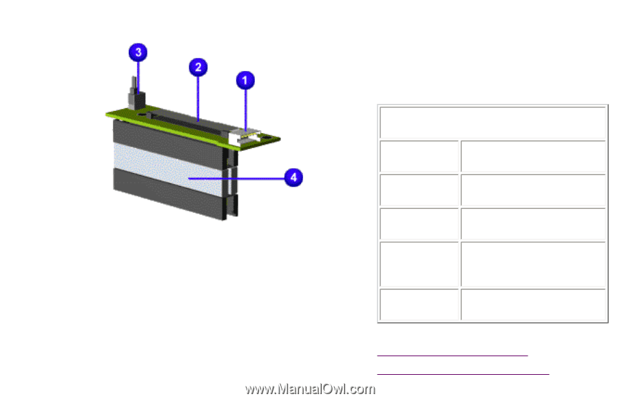
The following illustration and table
indicates the locations of the connectors
on the interface board.
Interface Board Components
Designator
Connector
1. JP1
Backlight Switch
2. JP3
Display Interface ZIF
3. JP4
Inverter/Backlight LIF
Connector
4. None
Interface Header
Return to Removal &
Replacement Procedures