Compaq Presario 1900 Presario 1900 Series Maintenance and Service Guide - Page 39
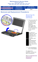
Preparing the Computer for Disassembly
 |
View all Compaq Presario 1900 manuals
Add to My Manuals
Save this manual to your list of manuals |
Page 39 highlights
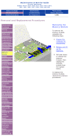
Before You Begin Removal Sequence Product Description Maintenance & Service Guide Presario 1900 Series Models: 1900T, 1905, 1906, 1910, 1915, 1919, 1920, 1922, 1925, 1926, 1927, 1928, 1929, and 1930 Specifications Troubleshooting Pin Assignments Parts Catalog Battery Operations Index Removal and Replacement Procedures Electrostatic Preparing the Computer for Disassembly Discharge Service Before beginning removal and replacement procedures, complete the following procedures: Considerations 1. Disconnect AC power and any external devices. Cables and Connectors 2. Remove the battery pack. Preparing the Computer for Disassembly Battery Pack Hard Drive 3. Remove any PC Cards. 4. Remove the wedge. The battery pack should be removed before performing any internal maintenance on IMPORTANT: the computer. Keyboard Memory Module Modem Heatspreader Processor WARNING: Metal objects can damage the battery pack as well as the battery contacts in the battery compartment. To prevent damage, do not allow metal objects to touch the battery contacts. Place only the battery pack for the Compaq Presario 1900 Series Portable Computers into the battery compartment. Do not force the battery pack into the bay if insertion does not occur easily. Display Panel Assembly Upper CPU Cover with Palmrest and TouchPad CAUTION: Do not crush, puncture, or incinerate the battery pack. Do not open a battery pack, as this damages the pack, makes it unusable, and exposes potentially harmful battery components. There are no field-serviceable parts located inside the battery pack. Hard Drive/ Battery Charger Board Converter Board Low Voltage Differential Signal Board The Compaq Presario 1900 Series Portable Computers have several screws of various sizes which are not interchangeable. Care must be taken during reassembly to ensure that the NOTE: correct screws are used in their correct location. During removal please keep respective screws with their associate sub-assembly. Fan Assembly System Board Speaker Assembly Disassembling the Wedge DVD or CD Drive System to Wedge Interface Board Diskette Drive Wedge to Port Replicator Interface Board How to use Processor Jig
-
 1
1 -
2
-
3
-
4
-
5
-
6
-
7
-
8
-
9
-
10
-
11
-
12
-
13
-
14
-
15
-
16
-
17
-
18
-
19
-
20
-
21
-
22
-
23
-
24
-
25
-
26
-
27
-
28
-
29
-
30
-
31
-
32
-
33
-
 34
34 -
 35
35 -
 36
36 -
 37
37 -
 38
38 -
 39
39 -
 40
40 -
 41
41 -
 42
42 -
 43
43 -
 44
44 -
45
-
46
-
47
-
48
-
49
-
50
-
51
-
52
-
53
-
54
-
55
-
56
-
57
-
58
-
59
-
60
-
61
-
62
-
63
-
64
-
65
-
66
-
67
-
68
-
69
-
70
-
71
-
72
-
73
-
74
-
75
-
76
-
77
-
78
-
79
-
80
-
81
-
82
-
83
-
84
-
85
-
86
-
87
-
88
-
89
-
90
-
91
-
92
-
93
-
94
 |
 |