Compaq R6000 Technology for remote management of power distribution - Page 4
Implementation strategies, Power distribution strategies
 |
UPC - 743172638854
View all Compaq R6000 manuals
Add to My Manuals
Save this manual to your list of manuals |
Page 4 highlights
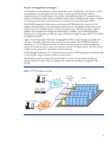
Implementation strategies Zoned power distribution systems offer greater flexibility for load balancing and for precise circuit monitoring. The HP PDR supports a variety of strategies for power distribution and management. Power distribution strategies With two distribution panels each with an AC input, the HP PDR supports a number of possible distribution scenarios. Figure 4 shows two basic configurations: single bus power for a row of IT racks and dual bus power to a row of IT racks. In a single-bus configuration (Figure 4A), the PDR receives the load from the AC mains and each distribution panel (DP 1or DP 2) provides power to specific ITE racks in the row. Backup power for the row would typically be provided from uninterruptible power supplies (UPSs) on both mains directly before the PDR. In a dual-bus configuration (Figure 4B), each distribution panel provides the full load of power from an AC bus to all racks in the row. Backup power for the row could be provided from UPSs before or after the PDR on the power bus designated to have redundancy. Actual configurations depend on the specific power requirements of the each IT equipment rack. Zoning allows each row to be uniquely configured based on ITE rack contents and redundancy requirements. Figure 4. HP PDR power distribution configurations A: Single-bus power AC Mains PDR DP 1 DP 2 ITE Rack ITE Rack ITE Rack ITE Rack ITE Rack ITE Rack AC Bus A AC Bus B B: Dual-bus power PDR DP 1 ITE Rack ITE Rack ITE Rack ITE Rack ITE Rack ITE Rack DP 2 4
-
 1
1 -
 2
2 -
 3
3 -
 4
4 -
 5
5 -
 6
6 -
 7
7 -
 8
8 -
 9
9 -
 10
10 -
11
-
12
 |
 |
