Compaq dx1000 Service Reference Guide: Compaq dx1000 Microtower PC - Page 44
Cable Connections, System Board Connections
 |
View all Compaq dx1000 manuals
Add to My Manuals
Save this manual to your list of manuals |
Page 44 highlights
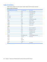
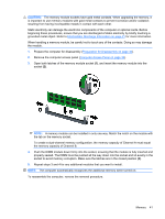
Cable Connections System board connectors are color-coded to make it easier to find the proper connection. System Board Connections System Board Connector Name ATX1 JPW1 FDD1 CPU_FAN1 SYS_FAN1 JFP1 FUSB1 FUSB2 JAUD1 DIMM1 DIMM2 PCI1 PCI_E1 PCI_E2 PCI_E3 U1 CMOS SATA0 SATA1 SATA2 SATA3 BAT1 Connector Color white white black white red black white white yellow blue blue white black black black silver black with green cap dark blue white light blue orange black Description Power supply, 24-pin Power supply, 4-pin Diskette drive Heat sink fan Chassis fan Front power button/LED Front I/O USB Media card reader Front I/O audio Memory slots PCI 2.3 full-height slot PCI Express X16 slot PCI Express X1 slot PCI Express X1 slot Processor Clear CMOS/password header SATA drives RTC battery 38 Chapter 6 Removal and Replacement Procedures Microtower (MT) Chassis
-
 1
1 -
2
-
3
-
4
-
5
-
6
-
7
-
8
-
9
-
10
-
11
-
12
-
13
-
14
-
15
-
16
-
17
-
18
-
19
-
20
-
21
-
22
-
23
-
24
-
25
-
26
-
27
-
28
-
29
-
30
-
31
-
32
-
33
-
34
-
35
-
36
-
37
-
38
-
 39
39 -
 40
40 -
 41
41 -
 42
42 -
 43
43 -
 44
44 -
 45
45 -
 46
46 -
 47
47 -
 48
48 -
 49
49 -
50
-
51
-
52
-
53
-
54
-
55
-
56
-
57
-
58
-
59
-
60
-
61
-
62
-
63
-
64
-
65
-
66
-
67
-
68
-
69
-
70
-
71
-
72
-
73
-
74
-
75
-
76
-
77
-
78
-
79
-
80
-
81
-
82
-
83
-
84
-
85
-
86
-
87
-
88
-
89
-
90
-
91
-
92
-
93
-
94
-
95
-
96
-
97
-
98
 |
 |
