Craftsman 18180 Operation Manual - Page 3
Specifications, Nails, Air Supply Line, Loading - roofing nailer
 |
UPC - 026420181808
View all Craftsman 18180 manuals
Add to My Manuals
Save this manual to your list of manuals |
Page 3 highlights
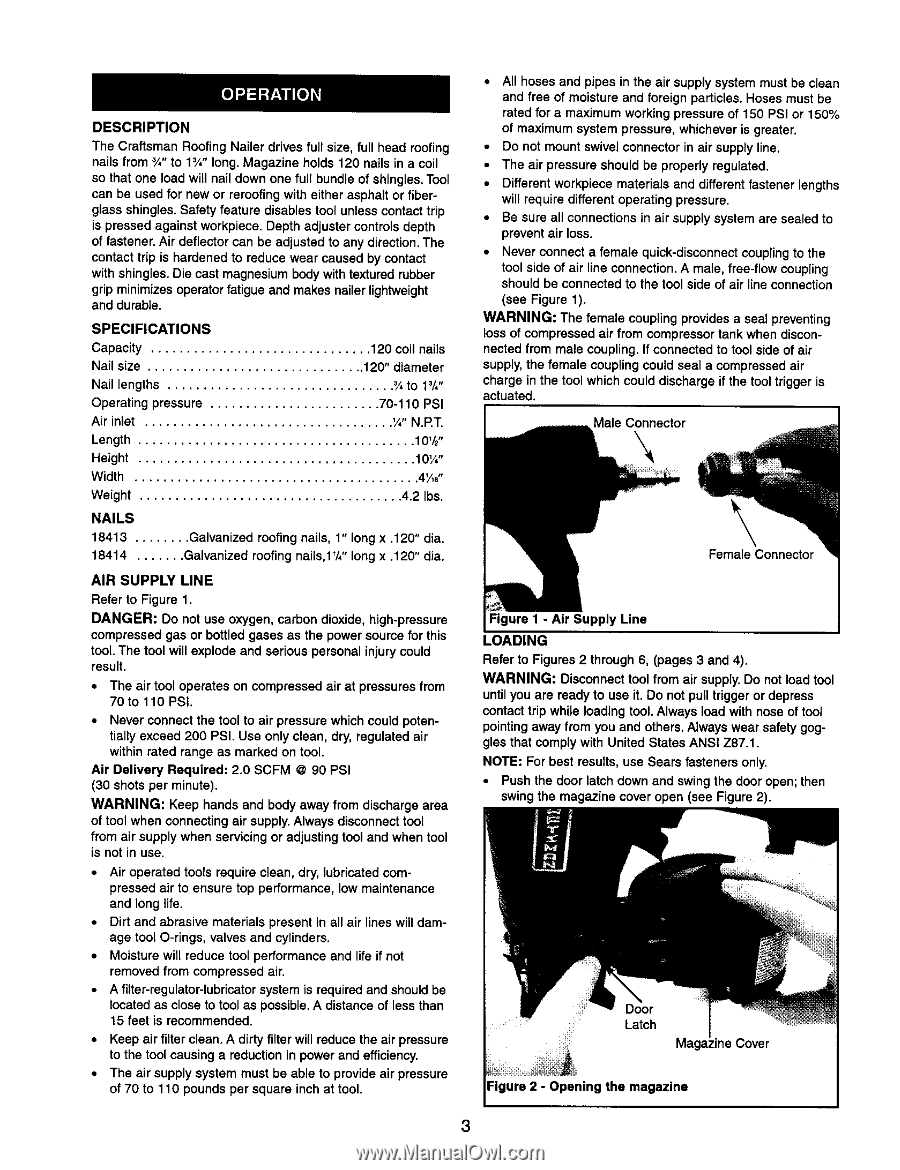
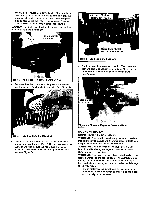
DESCRIPTION The Craftsman Roofing Nailer drives full size, full head roofing nails from _/,"to 13/", long. Magazine holds 120 nails in a coil so that one load will nail down one full bundle of shingles. Tool can be used for new or reroofing with either asphalt or fiberglass shingles. Safety feature disables tool unless contact trip is pressed against workpiece. Depth adjuster controls depth of fastener. Air deflector can be adjusted to any direction.The contact trip is hardened to reduce wear caused by contact with shingles. Die cast magnesium body with textured rubber grip minimizes operator fatigue and makes nailer lightweight and durable. SPECIFICATIONS Capacity Nail size 120 coil nails 120" diameter Nail lengths Operating pressure Air inlet 3/_to 13/", 70-110 PSI '/," N.RT. Length Height Width Weight NAILS 10'/_" 10W' 4¼6" 4.2 Ibs. 18413 ........ Galvanized roofing nails, 1" long x .120" dia. 18414 ....... Galvanized roofing nails,1 _/4"long x .120" dia. AIR SUPPLY LINE Refer to Figure 1. DANGER: Do not use oxygen, carbon dioxide, high-pressure compressed gas or bottled gases as the power source for this tool. The tool will explode and serious personal injury could result. • The air tool operates on compressed air at pressures from 70to 110 PSI. • Never connect the tool to air pressure which could potentially exceed 200 PSI. Use only clean, dry, regulated air within rated range as marked on tool. Air Delivery Required: 2.0 SCFM @ 90 PSI (30 shots per minute). WARNING: Keep hands and body away from discharge area of tool when connecting air supply. Always disconnecttool from air supply when servicing or adjusting tool and when tool is not in use. • Air operated tools require clean, dry, lubricated compressed air to ensure top performance, low maintenance and long life. • Dirt and abrasive materials present in all air lines will damage tool O-rings, valves and cylinders. • Moisture will reduce tool performance and life if not removed from compressed air. • A fUter-regulator-lubricator system is required and should be located as close to tool as possible. A distance of less than 15 feet is recommended. • Keep air filter clean. A dirty filter will reduce the air pressure to the tool causing a reduction in power and efficiency. • The air supply system must be able to provide air pressure of 70 to 110 pounds per square inch at tool. • All hoses and pipes in the air supply system must be clean and free of moisture and foreign particles. Hoses must be rated for a maximum working pressure of 150 PSI or 150% of maximum system pressure, whichever is greater. • Do not mount swivel connector in air supply line. • The air pressure should be properly regulated. • Different workpiece materials and different fastener lengths will require different operating pressure. • Be sure all connections in air supply system are sealed to prevent air loss. • Never connect a female quick-disconnect couplingto the tool side of air line connection. A male, free-flow coupling should be connected to the tool side of air line connection (see Figure 1). WARNING: The female coupling provides a seal preventing bossof compressed air from compressor tank when disconnected from male coupling. If connected to tool side of air supply, the female coupling could seal a compressed air charge in the tool which could discharge if the tool trigger is actuated. Male Connector \ Female Connector Figure I - Air Supply Line LOADING Refer to Figures 2 through 6, (pages 3 and 4). WARNING: Disconnect tool from air supply. Do not load tool until you are ready to use it. Do not pull trigger or depress contact trip while loading tool. Always load with nose of tool pointing away from you and others. Always wear safety goggles that comply with United States ANSI Z87.1. NOTE: For best results, use Sears fasteners only. Push the door latch down and swing the door open; then swing the magazine cover open (see Figure 2). Door Latch line Cover Figure 2 - Opening the magazine 3
-
 1
1 -
 2
2 -
 3
3 -
 4
4 -
 5
5 -
 6
6 -
 7
7 -
 8
8 -
 9
9 -
10
-
11
-
12
-
13
-
14
-
15
-
16
 |
 |