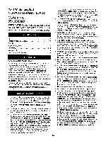
Craftsman 18180 Operation Manual - Page 7
Check ratchet jaws Fig. 10, Nos. 61
 |
UPC - 026420181808
View all Craftsman 18180 manuals
Add to My Manuals
Save this manual to your list of manuals |
Page 7 highlights
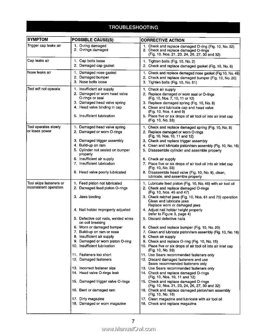
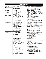
SYMPTOM Trigger cap leaks air Cap leaks air Nose leaks air Tool will not operate Tool operates slowly or loses power Tool skips fasteners or inconsistent operation POSSIBLE CAUSE(S) 1. O-ring damaged 2. O-rings damaged 1. Cap bolts loose 2. Damaged cap gasket 1. Damaged nose gasket 2. Damaged bumper 3, Nose bolts loose 1. Insufficientair supply 2. Damaged or worn head valve O-rings or seal 3. Damaged head valve spring 4. Head valve binding in cap 5. Insufficient lubrication 1. Damaged head valve spring 2. Damaged or worn O-rings 3. Damaged trigger assembly 4. Build-up on ram 5. Cylinder not sealed on bumper properly 6. Insufficient air supply 7. Insufficient lubrication 8. Head valve poorly lubricated 1. Feed piston not lubricated 2. Damaged feed piston O-rings 3, Jaws binding 4. Nail holder improperly adjusted 5. Defective coil nails, welded wires on coil breaking 6. Worn or damaged bumper 7. Build-up on ram or nose 8. Insufficient air supply 9. Damaged or worn piston O-ring 10. Insufficient lubrication 11. Fasteners too short 12. Damaged fasteners 13. Incorrect fastener size 14. Head valve O-rings leak 15. Damaged trigger valve O-rings 16. Bent or damaged ram 17. Dirty magazine 18. Damaged or worn magazine CORRECTIVE ACTION 1. Check and replace damaged O-ring (Fig. 10, No. 32) 2. Check and replace damaged O-rings (Fig. 10, Nos. 21,23, 24, 26, 27, 30 and 32) 1. Tighten bolts (Fig. 10, No. 2) 2. Check and replace damaged gasket (Fig. 10, No. 6) 1. Check and replace damaged nose gasket (Fig.lO, No. 48 2. Check and replace damaged bumper (Fig. 10, No. 20) 3. Tighten bolts (Fig. 10, No, 51) 1. Check air supply 2. Replace damaged or worn seal or O-rings (Fig. 10, Nos. 7, 10, 11 or 12) 3. Replace damaged spring (Fig. 10, No. 8) 4. Clean and lubricate cap and head valve (Fig. 10, Nos. 4 and 9) 5. Place five or six drops of air tool oil into air inlet cap (Fig. 10, No. 33) 1. Check and replace damaged spring (Fig. 10, No. 8) 2. Replace damaged or worn O-rings (Fig. 10, Nos. 10, 11 and 12) 3. Check and replace trigger assembly 4. Clean and lubricate piston/ram assembly (Fig. 10, No. 16) 5. Disassemble cylinder and assemble properly 6. Check air supply 7. Place five or six drops of air tool oil into air inlet cap (Fig. 10, No. 33) 8. Disassemble head valve (Fig. 10, No. 9), clean, lubricate, and assemble properly 1, Lubricate feed piston (Fig. 10, No. 46) with air tool oil 2. Check and replace damaged O-rings (Fig. 10, Nos. 45 and 47) 3, Check ratchet jaws (Fig. 10, Nos. 61 and 70) operation Clean and lubricate jaws Replace worn or damaged jaws 4. Adjust nail holder height properly (refer to Figure 3, page 4) 5. Discard defective nails 6. Check and replace bumper (Fig. 10, No. 20) 7. Clean and lubricate piston/ramassembly (Fig. 10, No. 16) 8. Check air supply 9. Check and replace O-ring (Fig. 10, No. 15) 10. Place five or six drops of air tool oil into air inlet cap (Fig. 10, No. 33) 11. Use Sears recommended fasteners only 12. Discard damaged fasteners and use Sears recommended fasteners only 13. Use Sears recommended fasteners only 14. Check and replace damaged O-rings (Fig. 10, Nos. 10, 11 and 12) t5. Check and replace damaged O-rings (Fig. 10, Nos. 21, 23, 24, 26, 27, 30 and 32) 16. Check and replace damaged piston/ram assembly (Fig. 10, No. 16) 17. Clean magazine and lubricate with air tool oil 18. Check and replace magazine 7
-
 1
1 -
 2
2 -
 3
3 -
 4
4 -
 5
5 -
 6
6 -
 7
7 -
 8
8 -
 9
9 -
 10
10 -
 11
11 -
 12
12 -
13
-
14
-
15
-
16
 |
 |