Craftsman 21154 Owners Manual - Page 11
Spark Arrestors, Fig. G
 |
View all Craftsman 21154 manuals
Add to My Manuals
Save this manual to your list of manuals |
Page 11 highlights
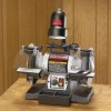
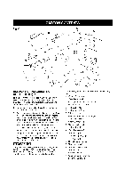
SPARK ARRESTORS (Fig. G) 1, Assemble the Spark Arrestors (A) to the inside surface of the Wheel Covers (B) with the hex head screws with washers (C) as shown. See Figure G. 2. Adjust each Spark Arrestor until the lower edge (E) is 1/16" from the grinding wheel. Firmly tighten the hex head screws. See Figure G. Fig. G B E WORK LIGHT (Fig. J) The Bench Grinder is provided with a Flexible Work Light to assist in visibility of the workpiece. The Bench Grinder is NOT provided with a light bulb for the Flexible Work Light. W!Ikvlv/_;41_11_[€! To reduce the risk of fire, use a 120 volt, 40 Watt or less Track Light Bulb, Type R20, medium base or equivalent (not included). DO NOT use a light bulb that extends past the end of the light housing. The Flexible Work Light may be turned "ON" or "OFF" by using the rotary switch (B) on the top surface of the housing (A). The switch can be rotated in the clockwise direction only. See Figure J. NOTE: The Flexible Work Light can be turned "ON" or "OFF" even if the Bench Grinder is turned "OFF". CAUTION: The Flexible Work Light housing will remain hot for a few minutes after turning it "OFF". Avoid contact with housing until it is cool. Fig. J B EYESHIELDS (Fig. H) A 1, Assemble the eyeshield (C) to the Spark Arrestor (A) inserting carriage head screw (B) through Eyeshield and the Spark Arrestor as shown. See Figure H. 2. Assemble the flat washer (D), lock washer (F) and Lock Knob (E) to the carriage head screw and tighten until the Eyeshield remains in the desired position. See Figure H. B Fig. H D EF C 11
-
 1
1 -
2
-
3
-
4
-
5
-
 6
6 -
 7
7 -
 8
8 -
 9
9 -
 10
10 -
 11
11 -
 12
12 -
 13
13 -
 14
14 -
 15
15 -
 16
16 -
17
-
18
-
19
-
20
-
21
-
22
-
23
-
24
-
25
-
26
-
27
-
28
-
29
-
30
-
31
-
32
-
33
-
34
-
35
-
36
 |
 |
