Craftsman 21154 Owners Manual - Page 14
Using, The Wheel, Dresser, Fig. M
 |
View all Craftsman 21154 manuals
Add to My Manuals
Save this manual to your list of manuals |
Page 14 highlights
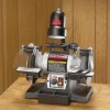
USING THE WHEEL DRESSER (Fig. M) Fig. M D A B CHANGING (Fig. N) Fig. N E B THE GRINDING C H I WHEEL G The Wheel Dresser is to be used on the grinding wheels. It will remove buildup up of material on the grinding wheel, remove imperfections and make the corners of the grinding wheel square. See Figure M. DO NOT use the Wheel Dresser on the Wire Wheel. 1, If the optional Drill Bit Sharpening Accessory Plate was installed earlier, remove it and reassemble the right side tool rest (A) and adjust it until it is in the flat horizontal position as shown and 1/16" away from the grinding wheel. 2, Turn "ON" the Bench Grinder. and then turn the Variable Speed Switch clockwise until solid resistance is felt. Let the grinding wheel come up to a steady speed for one minute. 3, After the grinding wheel has gotten to a steady speed, place the Wheel Dresser (B) flat on the Tool Rest with the serrated wheels facing the grinding wheel. 4, Firmly hold on to the handle of the WheelDresser (B). 5. Move the Wheel Dresser forward until the serrated wheels (D) make light contact with the grinding wheel (C). After contact has been made, slide the Wheel Dresser side to side across the Tool Rest to dress the grinding wheel until the edge of the grinding wheel is square and the surface is clean. 6, After the operator has completed dressing the grinding wheel, turn "OFF" the Bench Grinder and let the grinding wheel come to a complete stop. 7, Inspect the grinding wheel for any damage! 8. The grinding wheel may now be slightly smaller in diameter after dressing. Readjust the tool rests and spark arrestors to maintain a 1/16" clearance to the grinding wheel. Due to normal wear, both wheels will need to be replaced occasionally. 1. Turn the power switch OFF and unplug the power cord from its power source. 2. Rotate the eyeshield up to access the tool rest. 3. Loosen the tool rest knob and rotate the tool rest away from the grinding wheel. 4. Remove three Knobs (A) from guard completely. See Figure N. 5. Remove Wheel Cover (B). Fig. O D F 6, Place a Crescent Wrench (D) (not included), Figure O, on the arbor hex nut (E), Figure N. Place the box end of the Special Wrench (F), Figure O (included with your grinder) onto the flats of the arbor shaft (G). 14
-
 1
1 -
2
-
3
-
4
-
5
-
6
-
7
-
8
-
 9
9 -
 10
10 -
 11
11 -
 12
12 -
 13
13 -
 14
14 -
 15
15 -
 16
16 -
 17
17 -
 18
18 -
 19
19 -
20
-
21
-
22
-
23
-
24
-
25
-
26
-
27
-
28
-
29
-
30
-
31
-
32
-
33
-
34
-
35
-
36
 |
 |
