Craftsman 25cc Operation Manual - Page 16
Large Bump Feed Head .095 Line - straight shaft trimmer
 |
View all Craftsman 25cc manuals
Add to My Manuals
Save this manual to your list of manuals |
Page 16 highlights
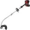
MAINTENANCE TRIMMER HEAD LINE INSTALLATION LARGE BUMP FEED HEAD (.095" Line) 1. Lock shaft by inserting allen key into groove. Loosen by turning head as shown for straight shaft. If your model is a curved shaft, loosen by turning opposite the direction shown in (Fig. 31). 2. Depress tab and twist trimmer head body CW to disassemble (Fig. 32). 6. Snap the free length of lines into top grooves in reel and pull through holes on trimmer head body (Fig. 34 and Fig. 35). Trimmer Head Body Holes Spring Reel Bump Feed Button Fig.31 Top view Fig 35 Trimmer Head Body Bottom 7. Close assembly in sequence as shown in (Fig. 35). Tab 8. Reassemble by lining up the 4 tabs on trimmer head body and bottom. Turn CCW until "click" (Fig. 36). Top view Tab "click" Trimmer Head Body Fig.32 3. If using new line from a bulk spool, cut 2 pieces of line 7.5' (2.28 m) long. Insert each line into one of the holes on each retention hook opposite of the direc tion of the rotation about 1/2 in (12-7 mm) deep. 4. Wrap line 180° and wind extra line in the opposite direction of rotation of the head (Fig. 33). Retention Hook Fig.36 9. Insert allen key into hole, tighten head by turning as shown for curved shaft and opposite for straight shaft (Fig. 37). Fig.33 5. Wind cord in direction indicated (CW) leaving 6 in (15-20 cm) access to pull through holes trimmer head body (Fig. 34). Fig.34 Snap to groove to pull through cover 16 LEHR | ALL RIGHTS RESERVED 2008-2009 Fig.3 7
-
 1
1 -
2
-
3
-
4
-
5
-
6
-
7
-
8
-
9
-
10
-
 11
11 -
 12
12 -
 13
13 -
 14
14 -
 15
15 -
 16
16 -
 17
17 -
 18
18 -
 19
19 -
 20
20 -
 21
21 -
22
 |
 |
