Craftsman 28986 Operation Manual - Page 31
Brake, Adjustment, Battery, Charging, Engine, Adjustments
 |
View all Craftsman 28986 manuals
Add to My Manuals
Save this manual to your list of manuals |
Page 31 highlights
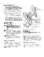
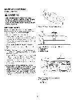
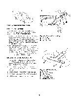
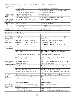
BRAKE ADJUSTMENT 1. Stop the unit, set the ground speed levers to START/PARK positions, set the parking brake lever to the ENGAGE position, turn the ignition OFF, and wait for all moving parts to stop. Remove the key. 2. Set both transmission release levers to the PUSH position. (Refer to "Pushing the Rider by Hand".) 3. Push the rider forward to make sure both transmission brakes are fully engaged and both rear wheels are locked in the stationary position (no rotation). 4. Locate the brake rod (A, Figure 36) and adjustment nut (B). 5. Measure the parking brake spring. Its compressed length, with the parking brake lever in the ENGAGE position, should be 3-1/2" (8,89 cm). Adjust the spring length by turning the adjustment nut (B), if necessary. 3-1/2" (8,89 cm) WARNING Corrosion hazard. Batteries contain acid. Always keep the battery upright and do not spill the electrolyte. Avoid contact with skin and eyes. Explosion hazard. Changing the battery produces explosive hydrogen gas. Only charge the battery in a well ventilated area, away from any ignition source such as a water heater, electric motor, or a lit cigarette. Wear Protective Equipment Always wear gloves and safety glasses when handling the battery and battery cables. BATTERY CHARGING A dead battery or one too weak to start the engine may be the result of a defect in the charging system or other electrical component. If there is any doubt about the cause of the problem, contact your local dealer. If you need to replace the battery, follow the steps under Cleaning the Battery & Cables in the Regular Maintenance Section. Figure 36. Brake Adjustment A. Brake Rod B. Adjustment Nut C. Return Spring (Removed for Illustration Only) D. Return Spring Hole To charge the battery, follow the instructions provided by the battery charger manufacturer as well as all warnings included in the safety rules sections of this book. Charge the battery until fully charged (until the specific gravity of the electrolyte is 1.250 or higher and the electrolyte temperature is at least 60 ° F). Do not charge at a rate higher than 10 amps. ENGINE ADJUSTMENTS The engine is designed to deliver the correct performance under all operating conditions. Any adjustments must be performed by a Sears or other qualified service dealer. 31
-
 1
1 -
2
-
3
-
4
-
5
-
6
-
7
-
8
-
9
-
10
-
11
-
12
-
13
-
14
-
15
-
16
-
17
-
18
-
19
-
20
-
21
-
22
-
23
-
24
-
25
-
 26
26 -
 27
27 -
 28
28 -
 29
29 -
 30
30 -
 31
31 -
 32
32 -
 33
33 -
 34
34 -
 35
35 -
 36
36 -
37
-
38
-
39
-
40
-
41
-
42
-
43
-
44
-
45
-
46
-
47
-
48
-
49
-
50
-
51
-
52
-
53
-
54
-
55
-
56
-
57
-
58
-
59
-
60
-
61
-
62
-
63
-
64
-
65
-
66
-
67
-
68
-
69
-
70
-
71
-
72
-
73
-
74
-
75
-
76
-
77
-
78
-
79
-
80
-
81
-
82
-
83
-
84
-
85
-
86
-
87
-
88
-
89
-
90
-
91
-
92
-
93
-
94
-
95
-
96
-
97
-
98
-
99
-
100
-
101
-
102
-
103
-
104
-
105
-
106
-
107
-
108
-
109
-
110
-
111
-
112
-
113
-
114
-
115
-
116
 |
 |
