Craftsman 30084N Operation Manual - Page 10
Installing Work Clamp, Installing Gas Supply - tools
 |
UPC - 055249070420
View all Craftsman 30084N manuals
Add to My Manuals
Save this manual to your list of manuals |
Page 10 highlights
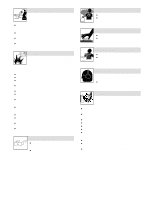
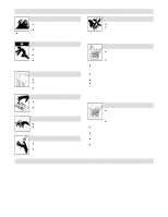
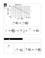
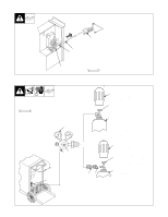
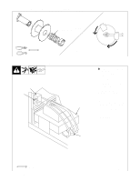
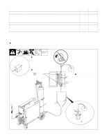
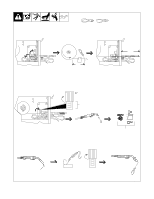
2-5. Installing Work Clamp 1 2 4 5 1 Work Cable 2 Boot Slide boot onto work cable. Route cable out front panel opening from inside. 3 Negative (-) Output Terminal Connect cable to terminal and cover connection with boot. 4 Hardware 5 Work Clamp Route cable through clamp handle and secure as shown. Close door. 3 2-6. Installing Gas Supply Tools Needed: 5/8, 1-1/8 in 4 7 5 6 Tools Needed: 1/2, 3/4 in ST-801 566-A OR 8 1 2 3 Argon Gas 1 2 3 9 CO2 Gas Obtain gas cylinder and chain to running gear, wall, or other stationary support so cylinder cannot fall and break off valve. 1 Cap 2 Cylinder Valve Remove cap, stand to side of valve, and open valve slightly. Gas flow blows dust and dirt from valve. Close valve. 3 Cylinder 4 Regulator/Flowmeter Install so face is vertical. 5 Regulator/Flowmeter Gas Hose Connection 6 Welding Power Source Gas Hose Connection Connect customer supplied gas hose between regulator/flowmeter gas hose connection, and fitting on rear of welding power source. 7 Flow Adjust Typical flow rate is 20 cfh (cubic feet per hour). Check wire manufacturer's recommended flow rate. 8 CO2 Adapter (Customer Supplied) 9 O-Ring (Customer Supplied) Install adapter with O-ring between regulator/flowmeter and CO2 cylinder. OM-194 199 Page 7 ST-801 571 / ST-802 028
-
 1
1 -
2
-
3
-
4
-
 5
5 -
 6
6 -
 7
7 -
 8
8 -
 9
9 -
 10
10 -
 11
11 -
 12
12 -
 13
13 -
 14
14 -
 15
15 -
16
-
17
-
18
-
19
-
20
-
21
-
22
-
23
-
24
-
25
-
26
-
27
-
28
-
29
-
30
-
31
-
32
-
33
-
34
-
35
-
36
-
37
-
38
-
39
-
40
-
41
-
42
-
43
-
44
-
45
-
46
-
47
-
48
-
49
-
50
-
51
-
52
-
53
-
54
-
55
-
56
-
57
-
58
-
59
-
60
-
61
-
62
-
63
-
64
-
65
-
66
-
67
-
68
 |
 |
