Craftsman 88830 Operation Manual - Page 21
forthbetweenthe R2positionandthe F6 positionseveraltimes.
 |
View all Craftsman 88830 manuals
Add to My Manuals
Save this manual to your list of manuals |
Page 21 highlights
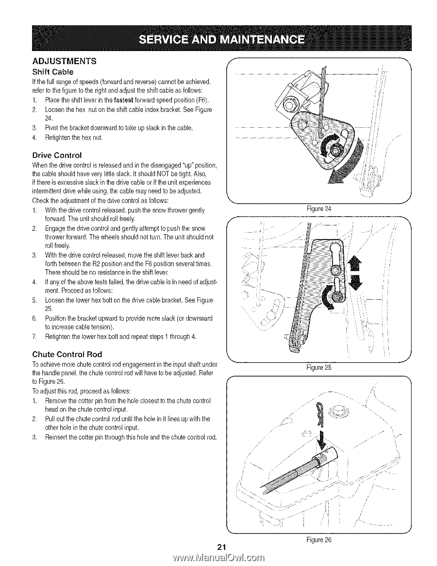
ADJUSTMENTS Shift Cable If thefull rangeof speeds(forwardand reverse)cannotbe achieved, referto the figureto the rightand adjustthe shift cableas follows: 1. Placethe shiftleverin thefastest forward speedposition(F6). 2. Loosenthe hex nuton the shiftcable indexbracket.See Figure 24. 3. Pivotthe bracketdownwardto take up slack in the cable. 4. Retightenthehex nut. Drive Control Whenthedrivecontrol is releasedand in thedisengaged"up"position, the cableshouldhavevery little slack.It shouldNOTbe tight. Also, if thereis excessiveslackin thedrive cableor if the unitexperiences intermittentdrivewhileusing,the cable mayneed to be adjusted. Checktheadjustmentof the drivecontrolas follows: 1. With thedrivecontrol released,pushthe snowthrowergently forward.The unitshouldroll freely. 2. Engagethe drivecontroland gently attemptto pushthe snow throwerforward.Thewheelsshouldnotturn. The unitshouldnot roll freely. 3. With thedrivecontrol released,movethe shift leverbackand forth betweenthe R2positionand the F6 positionseveraltimes. Thereshouldbe no resistancein the shiftlever. 4. If anyof the abovetests failed,the drivecable is in needof adjustment.Proceedas follows: 5. Loosenthe lowerhexbolt on the drivecable bracket.See Figure 25. 6. Positionthe bracketupwardto providemoreslack(or downward to increasecabletension). 7. Retightenthe lowerhex boltand repeatsteps1 through4. f ......... Chute Control Rod Toachievemorechutecontrolrod engagementin the input shaftunder the handlepanel,the chute controlrod will haveto be adjusted.Refer to Figure26. Toadjustthis rod,proceedas follows: 1. Removethecotterpin fromthe hole closestto the chute control headon thechute controlinput. 2. Pull outthe chute controlrod untilthe holein it lines up with the otherhole in the chute controlinput. 3. Reinsertthe cotterpin throughthis hole and thechute controlrod. J Figure25 J J \ \ / /, Figure26 21
-
 1
1 -
2
-
3
-
4
-
5
-
6
-
7
-
8
-
9
-
10
-
11
-
12
-
13
-
14
-
15
-
 16
16 -
 17
17 -
 18
18 -
 19
19 -
 20
20 -
 21
21 -
 22
22 -
 23
23 -
 24
24 -
 25
25 -
 26
26 -
27
-
28
-
29
-
30
-
31
-
32
-
33
-
34
-
35
-
36
-
37
-
38
-
39
-
40
-
41
-
42
-
43
-
44
-
45
-
46
-
47
-
48
-
49
-
50
-
51
-
52
-
53
-
54
-
55
-
56
-
57
-
58
-
59
-
60
-
61
-
62
-
63
-
64
-
65
-
66
-
67
-
68
-
69
-
70
-
71
-
72
 |
 |