Craftsman 88957 Operation Manual - Page 22
inthereverse
 |
View all Craftsman 88957 manuals
Add to My Manuals
Save this manual to your list of manuals |
Page 22 highlights
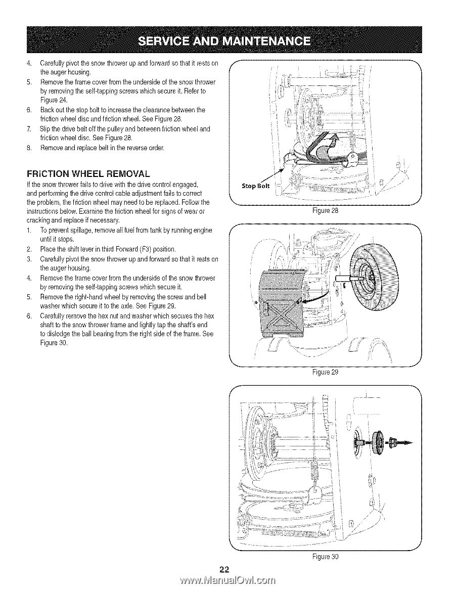
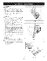
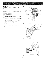
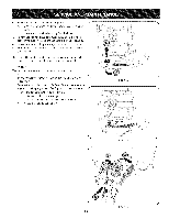
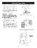
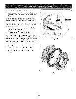
4, Carefupllyivotthesnowthrowueprandforwarsdothatitrestosn theaugehrousing. 5. Removtheeframceovefromtheundersiodfethesnowthrower byremovinthgeself-tappsincgrewwshicshecuriet.Refetor Figur2e4, 6. Backouthestopboltoincreastheeclearanbcetweethne frictiownheedliscandfrictiownheeSl,eeFigur2e8, 7. Slipthedrivebelot ffthepulleayndbetweefrnictiownheealnd frictiownheedliscS, eeFigur2e8, 8, Removaendreplacbeelitnthereversoerder, FRiCTiON WHEEL REMOVAL If the snowthrowerfailsto drive with thedrivecontrol engaged, and performingthe drivecontrolcableadjustmentfails to correct the problem,the frictionwheelmayneed to be replaced.Followthe instructionsbelow.Examinethe frictionwheelfor signsof wearor crackingand replaceif necessary. 1. Topreventspillage,removeall fuel fromtank by runningengine until it stops. 2. Placethe shiftleverin third Forward(F3) position. 3. Carefullypivotthe snowthrowerup and forwardso that it restson theauger housing. 4. Removethe frame coverfrom the undersideof the snow thrower by removingthe self-tappingscrewswhich secureit. 5. Removethe right-handwheelby removingthe screwand bell washerwhichsecureit to theaxle. See Figure29. 6. Carefullyremovethe hexnut and washerwhichsecuresthe hex shaftto the snowthrowerframeand lightlytap the shaft'send to dislodgethe ball bearingfrom the rightsideof theframe.See Figure30. Stop Bolt Figure28 J Figure29 f J Figure30 22
-
 1
1 -
2
-
3
-
4
-
5
-
6
-
7
-
8
-
9
-
10
-
11
-
12
-
13
-
14
-
15
-
16
-
 17
17 -
 18
18 -
 19
19 -
 20
20 -
 21
21 -
 22
22 -
 23
23 -
 24
24 -
 25
25 -
 26
26 -
 27
27 -
28
-
29
-
30
-
31
-
32
-
33
-
34
-
35
-
36
-
37
-
38
-
39
-
40
-
41
-
42
-
43
-
44
-
45
-
46
-
47
-
48
-
49
-
50
-
51
-
52
-
53
-
54
-
55
-
56
-
57
-
58
-
59
-
60
-
61
-
62
-
63
-
64
-
65
-
66
-
67
-
68
-
69
-
70
-
71
-
72
 |
 |