Cub Cadet 3X 30 HD 3X 26034 Operator's Manual - Page 10
Overhead Chute Control Assembly
 |
View all Cub Cadet 3X 30 HD manuals
Add to My Manuals
Save this manual to your list of manuals |
Page 10 highlights
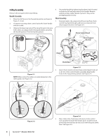
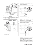
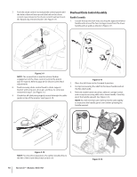
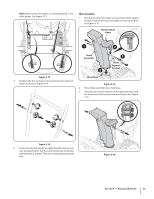
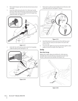
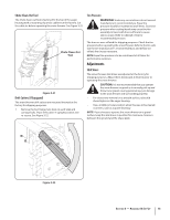
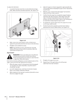
7. Push the chute control rod toward the control panel until the hole in the rod lines up with the hole in the chute control input closest to the chute control head and insert the hairpin clip removed earlier. See Figure 3-9. Overhead Chute Control Assembly Handle Assembly 1. Loosen the top two lock nuts securing the upper and lower handle and remove the two carriage screws from the lower handle and set aside as shown in Figure 3-11. Figure 3-9 NOTE: The second hole is used to achieve further engagement of the chute control rod into the pinion gear if required. Refer to page 24 for Chute Control Rod adjustments. Figure 3-11 2. Place the shift lever in the Forward-6 position. 8. Finish securing chute control head to chute support bracket with wing nut, clevis pin, and bow-tie cotter pin 3. Cut zip ties securing flex shaft to the lower handle and set the flex shaft aside. removed in step 1. See Figure 3-3. 4. Remove rubber bands securing cables to carriage screws 9. Check that all cables are properly routed through the cable guide on top of the engine. See Figure 3-10. and cut zip tie securing shift rod to lower handle. Carefully pivot the handle upward. See Figure 3-12. NOTE: You will need to lower shift rod to the side slightly to manuever the handle panel over it when pivoting the handle upward. Figure 3-10 NOTE: For smoothest operation, the cables should all be to the left of the chute directional control rod. 10 Section 3- Assembly & Set-Up Figure 3-12
-
 1
1 -
2
-
3
-
4
-
 5
5 -
 6
6 -
 7
7 -
 8
8 -
 9
9 -
 10
10 -
 11
11 -
 12
12 -
 13
13 -
 14
14 -
 15
15 -
16
-
17
-
18
-
19
-
20
-
21
-
22
-
23
-
24
-
25
-
26
-
27
-
28
 |
 |
