Cub Cadet 3X 30 HD 3X 26034 Operator's Manual - Page 14
Auger Control
 |
View all Cub Cadet 3X 30 HD manuals
Add to My Manuals
Save this manual to your list of manuals |
Page 14 highlights
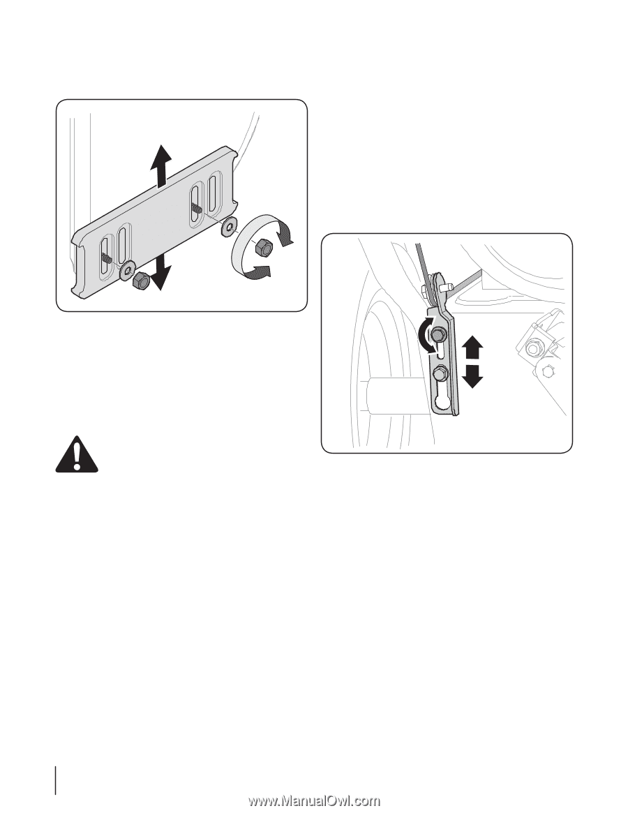
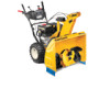
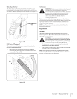
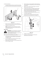
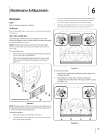
To adjust the skid shoes: 4. Allow the auger to remain engaged for approximately ten 1. Loosen the four hex nuts (two on each side) and carriage bolts. Move skid shoes to desired position. See Figure 3-23. (10) seconds before releasing the auger control. Repeat this several times. 5. With the auger control in the disengaged "up" position, walk to the front of the machine. 6. Confirm that the auger has completely stopped rotating and shows NO signs of motion. If the auger shows ANY signs of rotating, immediately return to the operator's position and shut off the engine. Wait for ALL moving parts to stop before readjusting the auger control. 7. To readjust the control cable, loosen the upper hex screw on the auger cable bracket. 8. Position the bracket upward to provide more slack (or downward to increase cable tension). See Figure 3-24. Figure 3-23 2. Make certain the entire bottom surface of skid shoe is against the ground to avoid uneven wear on the skid shoes. 3. Retighten nuts and bolts securely. NOTE: The skid shoes on your snow thrower may look slightly different (and have different hardware) than the ones shown in Figure 3-23. Auger Control WARNING! Prior to operating your snow thrower, carefully read and follow all instructions below. Perform all adjustments to verify your snow thrower is operating safely and properly. Refer to the Controls and Features section for the location of the auger control and check the adjustment as follows: 1. When the auger control is released and in the disengaged "up" position, the cable should have very little slack. It should NOT be tight. Figure 3-24 9. Retighten the upper hex screw. 10. Repeat steps 2 through 6 above to verify proper adjustment has been achieved. 2. In a well-ventilated area, start the snow thrower engine. Refer to your Engine Operator's Manual. 3. While standing in the operator's position (behind the snow thrower), engage the auger. 14 Section 3- Assembly & Set-Up
-
 1
1 -
2
-
3
-
4
-
5
-
6
-
7
-
8
-
 9
9 -
 10
10 -
 11
11 -
 12
12 -
 13
13 -
 14
14 -
 15
15 -
 16
16 -
 17
17 -
 18
18 -
 19
19 -
20
-
21
-
22
-
23
-
24
-
25
-
26
-
27
-
28
 |
 |