Cub Cadet 3X 30 HD 3X 26034 Operator's Manual - Page 11
Chute Assembly
 |
View all Cub Cadet 3X 30 HD manuals
Add to My Manuals
Save this manual to your list of manuals |
Page 11 highlights
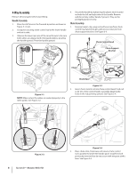
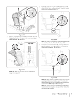
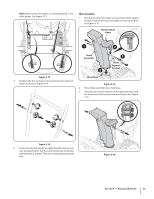
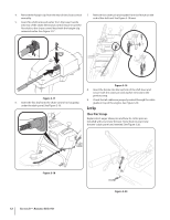
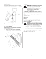
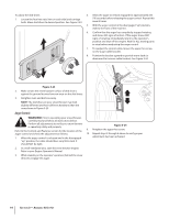
NOTE: Make certain the cables are seated properly in the roller guides. See Figure 3-13. Chute Assembly 1. Remove the lock nuts and hex screws from chute support bracket. Position the chute assembly over the chute base. See Figure 3-15. Chute Control Head 1 2 Figure 3-13 5. Reattach the two carriage screws and lock nuts removed earlier as shown in Figure 3-14. Chute Assembly 2 1 Chute Support Bracket Chute Base Figure 3-15 2. Place chute assembly onto chute base. 3. Secure chute control head to chute support bracket with the lock nuts and hex screws removed earlier. See Figure 3-16. Figure 3-14 6. Finish securing the handle by tightening the top two lock nuts loosened earlier. Remove and discard any remaining rubber bands, if present. They are for packaging purposes only. Figure 3-16 Section 3 - Assembly & Set-Up 11
-
 1
1 -
2
-
3
-
4
-
5
-
 6
6 -
 7
7 -
 8
8 -
 9
9 -
 10
10 -
 11
11 -
 12
12 -
 13
13 -
 14
14 -
 15
15 -
 16
16 -
17
-
18
-
19
-
20
-
21
-
22
-
23
-
24
-
25
-
26
-
27
-
28
 |
 |
