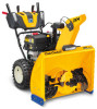
Cub Cadet 3X 30 inch HD Operation Manual - Page 16
Shave Plate, Auger Control, Shift Cable If Equipped
 |
View all Cub Cadet 3X 30 inch HD manuals
Add to My Manuals
Save this manual to your list of manuals |
Page 16 highlights
NOTE: If you choose to operate unit on a gravel surface, keep skid shoes in position for maximum clearance between ground and shave plate. To adjust skid shoes: 1. Loosen four hex nuts (a) (two on each side) and carriage bolts (b). Move skid shoes to desired position. See Figure 2-55. (b) (b) (a) (a) Figure 2-55 NOTE: The skid shoes on your unit may look slightly different (and have different hardware) than ones shown in Figure 2-55. 2. Make certain entire bottom surface of skid shoe is against ground to avoid uneven wear on skid shoes. 3. Retighten hex nuts (a) and carriage bolts (b) securely. Shave Plate NOTE: this procedure applies to units equipped with adjustable shave plates only. To adjust the shave plate: 1. Allow engine to run until it is out of fuel. Do not attempt to pour fuel from the engine. 2. Carefully pivot unit up and forward so that it rests on auger housing. 3. Loosen rear skid shoe bolts (a) on both sides of auger housing and remove carriage bolts (b) and hex nuts (c) which attach shave plate (d) to the bottom of the auger housing. See Figure 2-56. 4. Adjust the shave plate to one of 2 mounting positions. Reinstall and tighten the carriage bolts (b) and hex nuts (c) all bolts securely. See Figure 2-56. 5. Adjust the skid shoes. See Skid Shoes on page 15. Auger Control WARNING! Prior to operating your unit, carefully read and follow all instructions below. Perform all adjustments to verify your equipment is operating safely and properly. Refer to Controls & Operation section (page 18) for the location of auger control lever and check adjustment as follows: 1. When auger control lever is released and in disengaged "UP" position, the cable should have very little slack. It should NOT be tight. 2. In a well-ventilated area, start the snow thrower engine. Refer to your Engine Operator's Manual. 3. While standing in the operator's position (behind the unit), depress the auger control lever to engage auger. 4. Allow auger to remain engaged for approximately ten (10) seconds before releasing auger control lever. Repeat this several times. 5. With auger control lever in disengaged "UP" position, walk to front of machine. 6. Confirm that auger has completely stopped rotating and shows NO signs of motion. If auger shows ANY signs of rotating, immediately return to operator's position and shut OFF engine. Wait for ALL moving parts to stop before readjusting auger control lever. 7. To readjust the auger control cable, loosen upper hex screw (a) on all on units except the E-Z Chute™ unit auger control bracket. See Figure 2-57. 8. On E-Z Chute™ models, loosen the rear hex screw on the auger control bracket. See Figure 2-58. Figure 2-58 9. Position bracket upward on all units except the E-Z Chute™, push the adjustment bracket forward on those units to provide more slack (or downward/rearward to increase cable tension). See Figure 2-57 or Figure 2-58 depending on your unit. 10. Retighten upper/rear hex screw (a). 11. Repeat the steps 1 - 6 to verify proper adjustment has been achieved. Shift Cable (If Equipped) If full range of speeds (forward and reverse) cannot be achieved, adjust shift cable as follows: 1. Place shift lever in fastest forward speed position. 2. Loosen hex nut (a) on shift cable index bracket. See Figure 2-59. (a) (a) (a) (b) (b) (b) (b) (d) (c) (c) (c) (c) Figure 2-56 NOTE: 3-Stage unit shown. (a) Auger Control Bracket Figure 2-57 Figure 2-59 3. Pivot bracket downward to take up slack in cable. 4. Retighten hex nut. 16 Section 2 - Assembly & Set-Up
-
 1
1 -
2
-
3
-
4
-
5
-
6
-
7
-
8
-
9
-
10
-
 11
11 -
 12
12 -
 13
13 -
 14
14 -
 15
15 -
 16
16 -
 17
17 -
 18
18 -
 19
19 -
 20
20 -
 21
21 -
22
-
23
-
24
-
25
-
26
-
27
-
28
-
29
-
30
-
31
-
32
-
33
-
34
-
35
-
36
-
37
-
38
-
39
-
40
-
41
-
42
-
43
-
44
-
45
-
46
-
47
-
48
-
49
-
50
-
51
-
52
-
53
-
54
-
55
-
56
 |
 |
