Cub Cadet CSV 070 Operation Manual - Page 4
Assembly & Set-up - chipper shredder
 |
View all Cub Cadet CSV 070 manuals
Add to My Manuals
Save this manual to your list of manuals |
Page 4 highlights
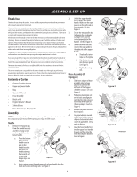
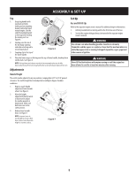
ASSEMBLY & SET-UP Thank You Thank you for purchasing this product. It was carefully engineered to provide excellent performance when properly operated and maintained. Please read this entire manual prior to operating the equipment. It instructs you how to safely and easily set up, operate and maintain your machine. Please be sure that you, and any other persons who will operate the machine, carefully follow the recommended safety practices at all times. Failure to do so could result in personal injury or property damage. All information in this manual is relative to the most recent product information available at the time of printing. Review this manual frequently to familiarize yourself with the machine, its features and operation. Please be aware that this Operator's Manual may cover a range of product specifications for various models. Characteristics and features discussed and/or illustrated in this manual may not be applicable to all models. We reserve the right to change product specifications, designs and equipment without notice and without incurring obligation. If applicable, the power testing information used to establish the power rating of the engine equipped on this machine can be found at www.opei.org or the engine manufacturer's web site. If you have any problems or questions concerning the machine, phone an authorized service dealer or contact us directly. Customer Support telephone numbers, website address and mailing address can be found in the separate supplement page. We want to ensure your complete satisfaction at all times. Throughout this manual, all references to right and left side of the machine are observed from the operating position. The engine manufacturer is responsible for all engine-related issues with regards to performance, power-rating, specifications, warranty and service. Please refer to the engine manufacturer's Owner's/ Operator's Manual, packed separately with your machine, for more information. Contents of Carton • Chipper/Shredder Vacuum • Upper and Lower Handle • Bag • Operator's Manual • Hose Assembly • Bottle of Oil • Engine Operator's Manual • Safety Glasses • Hose Extension (1 - If Equipped) Assembly NOTE: This unit is shipped without gasoline or oil in the engine. Fill up gasoline and oil as instructed in the accompanying engine manual BEFORE operating your chipper shredder vacuum. Handle 1. Remove the hairpin clips from the handle brackets and the carriage screws and wing nuts from the b lower handle. a. Place the bottom holes in lower handle over the pins on the handle brackets with notch in handle pointing downwards and secure with hairpin clips. See Figure 1. b a Figure 1 b. Insert carriage screws through upper hole in lower handle from the inside and secure with wing nuts. See Figure 1. 2. Unfold the upper handle until it aligns with lower handle. Make sure the rope guide is on the right side of upper handle. See A in Figure 2. 3. Secure the two handles by tightening the star knobs (carriage bolts must be seated properly into the handle). See B in Figure 2. 4. Loosen the wing nut that secures the rope guide to the right side of the upper handle. a. Slowly pull starter rope out of engine. b. Slip the starter rope into the rope guide. See Figure 3. c. Tighten the wing nut. Hose Assembly (If Equipped) 1. Slide hose adapter of hose assembly into the base adapter located on the left front of the chipper shredder vacuum. See a in Figure 4. 2. Pull spring loaded pin out on the base and align pin with the first hole (closest to the end of the tube) in the hose adapter. See b in Figure 4. 3. Release the pin to lock the hose in place. 4. Lay hose tubing in curved end of hose handle next to chipper chute and into hose cradle (if applicable). See a and b in Figure 5. 5. Snap the hose handle first into the upper hose handle bracket and then into the lower hose handle bracket. See c in Figure 5. 4 b a Figure 2 b a c Figure 3 a Align Pin b with this Hole Figure 4 † If Equipped c a b† Figure 5
-
 1
1 -
 2
2 -
 3
3 -
 4
4 -
 5
5 -
 6
6 -
 7
7 -
 8
8 -
 9
9 -
 10
10 -
11
-
12
-
13
-
14
-
15
-
16
-
17
-
18
-
19
-
20
 |
 |
