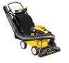
Cub Cadet CSV 070 Operation Manual - Page 6
Controls & Operation - chipper shredder vac
 |
View all Cub Cadet CSV 070 manuals
Add to My Manuals
Save this manual to your list of manuals |
Page 6 highlights
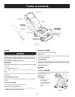
CONTROLS & OPERATION Drive Control (070) Recoil Starter Bag Hose Handle (050, 060, 070) Hose Extension (060, 070) Chipper Chute Nozzle Height Adjustment Lever Figure 8 Hose Assembly (050, 060, 070) Nozzle/Hose Vac Lever (050, 060, 070) Nozzle Controls WARNING The operation of any chipper shredder can result in foreign objects being thrown into the eyes, which can damage your eyes severely. Always wear the safety glasses provided with this unit or eye shields while operating or while performing any adjustments or repairs. Chipper Chute Allows twigs and small branches up to 1-1/2" in diameter to be fed into the impeller for chipping. Nozzle Height Adjustment Lever Used to adjust the nozzle ground clearance ranging approximately 5/8" to 4 1/8". Nozzle Yard waste such as leaves or pine needles can be vacuumed up through the nozzle for shredding. Hose Assembly (050, 060, 070) Used as an alternative to the nozzle to vacuum yard waste such as leaves or pine needles. Hose Extension (060, 070) Used to vacuum yard waste in hard to reach places of yard. Nozzle/Hose Vac Lever (050, 060, 070) The nozzle/hose vac handle is located on top of the nozzle. Use it to switch vacuum suction between the nozzle and the hose assembly. Hose Handle (050, 060, 070) Used to guide hose assembly when vacuuming. Recoil Starter The recoil starter is attached to the right upper handle. Stand behind unit and pull the recoil starter to start engine. Drive Control (070) Located on the underside of the upper handle, the drive control is used to engage/ disengage wheels. Fully squeeze the drive control against the handle to engage the wheels; release to disengage. (DO NOT SLIP CLUTCH) Operation Starting & Stopping Engine Refer to the Engine Operator's manual packed with your chipper/shredder vacuum for instructions on starting and stopping the engine. 2 To Empty Bag 1. Unhook bag straps from the lower handle. 4 2. Unsnap bag clip from the top of lower handle. See Figure 9. 3 1 Figure 9 6
-
 1
1 -
 2
2 -
 3
3 -
 4
4 -
 5
5 -
 6
6 -
 7
7 -
 8
8 -
 9
9 -
 10
10 -
 11
11 -
 12
12 -
13
-
14
-
15
-
16
-
17
-
18
-
19
-
20
 |
 |
