Cub Cadet GTX 2100 GTX 2100 Operator's Manual - Page 22
Pivot Bar Adjustment
 |
View all Cub Cadet GTX 2100 manuals
Add to My Manuals
Save this manual to your list of manuals |
Page 22 highlights
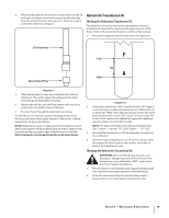
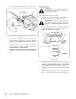
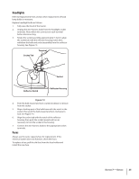
5. Loosen the jam nuts from the ball joints. See Figure 6-7. Pivot Bar Adjustment CAUTION: The tractor should be checked every 50 hours of operation for play between the frame channel and the pivot bar. Hex Lock Nut Steering Arm Jam Nut Ball Joint Drag Link Check and adjust the pivot axle as follows: 1. Raise the front of the tractor and set it on jack stands, so the front wheels are suspended above the ground. WARNING! When jacking up the front end of the tractor, always chock the rear wheels to prevent the tractor from rolling, tipping or sliding off the jack stands. 2. Move the ends of the pivot bar up and down to check for binding. If binding is present, loosen the lock nuts until binding is eliminated. See Figure 6-8. Adjustment Bolts Figure 6-7 6. Disconnect the front ball joints from the steering arms by removing the hex lock nuts. Refer to Figure 6-7. Manually move each wheel to achieve the required toe-in and equal D measurements. 7. Making sure not to move the steering gear or either wheel, turn the ball joint in or out on each drag linkas necessary to align with the hole in each steering arm. 8. Reinstall the ball joints in the steering arms and secure with the hex lock nuts. Tighten the jam nuts against the ball joints. Frame Channel Lock Nuts Pivot Bar Figure 6-8 3. Grasping the ends of the pivot bar, attempt to move each end of the axle forward and rearward to check for side play between the pivot bar and frame channel. If play is present, gradually tighten the lock nuts until play is minimized. 4. Repeat steps 2 and 3 until minimum play without binding is achieved. 5. Raise the front of the tractor, remove jack stands, and lower the tractor to the ground. Remove the blocks from the rear wheels. 22 Section 6 - Maintenance & Adjustments
-
 1
1 -
2
-
3
-
4
-
5
-
6
-
7
-
8
-
9
-
10
-
11
-
12
-
13
-
14
-
15
-
16
-
 17
17 -
 18
18 -
 19
19 -
 20
20 -
 21
21 -
 22
22 -
 23
23 -
 24
24 -
 25
25 -
 26
26 -
 27
27 -
28
-
29
-
30
-
31
-
32
 |
 |
