Cub Cadet GTX 2100 GTX 2100 Operator's Manual - Page 9
Assembly & Set-Up - accessories
 |
View all Cub Cadet GTX 2100 manuals
Add to My Manuals
Save this manual to your list of manuals |
Page 9 highlights
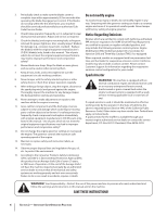
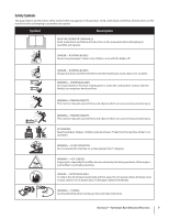
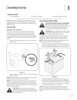
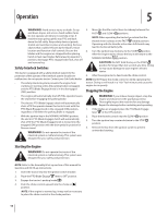
Assembly & Set-Up 3 Contents of Crate • One Garden Tractor • One Operator's Manual • One Engine Operator's Manual NOTE: This Operator's Manual covers several models. Tractor features may vary by model. Not all features in this manual are applicable to all tractor models and the tractor depicted may differ from yours. Tractor Set-Up Moving The Tractor Manually Your tractor's transmission is equipped with a hydrostatic relief valve for occasions when it is necessary to move the tractor manually. Opening this valve permits the fluid in the transmission to bypass its normal route, allowing the rear tires to "freewheel." To open the hydrostatic relief valve, proceed as follows: 1. Locate the hydrostatic bypass rod in the rear of the tractor. See Figure 3-1. Connecting the Battery Cables CALIFORNIA PROPOSITION 65 WARNING! Battery posts, terminals, and related accessories contain lead and lead compounds, chemicals known to the State of California to cause cancer and reproductive harm. Wash hands after handling. CAUTION: When attaching battery cables, always connect the POSITIVE (red) wire to its terminal first, followed by the NEGATIVE (black) wire. For shipping reasons, both battery cables on your equipment may have been left disconnected from the terminals at the factory. To connect the battery cables, proceed as follows: NOTE: The positive battery terminal is marked Positive (+). The negative battery terminal is marked Negative (-). 1. Remove the plastic cover, if present, from the positive (+) battery terminal and attach the red cable to the positive (+) battery terminal with the bolt and hex nut. See Figure 3-2. Figure 3-1 2. Pull the hydrostatic bypass rod down, outward and then up to lock it in place. NOTE: If the tractor will not move or does not move freely when pushing check if the bypass lever is fully open. NOTE: The transmission will NOT engage when the hydrostatic bypass rod is pulled out. Return the rod to its normal position prior to operating the tractor. If the tractor will not move when pushing on the forward/reverse pedals, or moves slowly, check to see of the bypass valve is on. CAUTION: Never attempt to move the tractor manually without first opening the hydrostatic relief valve. Doing so will result in serious damage to the tractor's transmission. Figure 3-2 2. Remove the plastic cover, if present, from the negative (-) battery terminal and attach the black cable to the negative (-) battery terminal with the bolt and hex nut. See Figure 3-2. 3. Position the red rubber boot over the positive (+) battery terminal to help protect it from corrosion. NOTE: If the battery is put into service after the date shown on top or side of battery, charge the battery as instructed in the Maintenance section your Operator's Manual prior to operating the tractor. 9
-
 1
1 -
2
-
3
-
 4
4 -
 5
5 -
 6
6 -
 7
7 -
 8
8 -
 9
9 -
 10
10 -
 11
11 -
 12
12 -
 13
13 -
 14
14 -
15
-
16
-
17
-
18
-
19
-
20
-
21
-
22
-
23
-
24
-
25
-
26
-
27
-
28
-
29
-
30
-
31
-
32
 |
 |