Cub Cadet LGT 1054 LGT 1050 Operator's Manual - Page 25
Cutting Blades - deck belt
 |
View all Cub Cadet LGT 1054 manuals
Add to My Manuals
Save this manual to your list of manuals |
Page 25 highlights
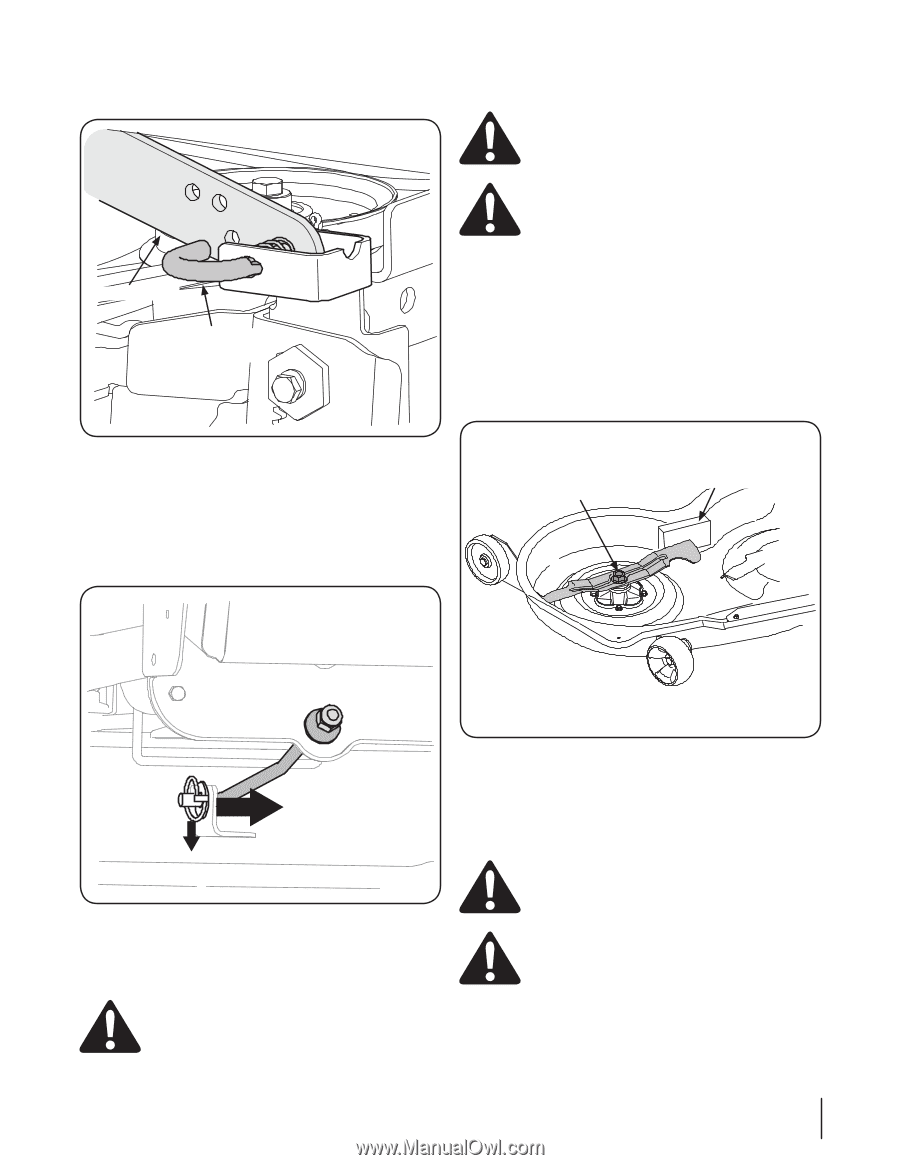
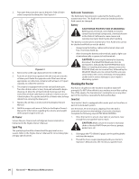
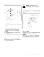
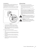
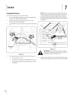
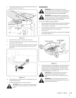
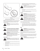
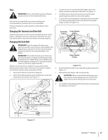
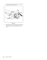
6. Pull the deck support pin outward to release the deck from the deck lift arm. See Figure 7-3. Deck Lift Arm Deck Support Pin Cutting Blades WARNING! Shut the engine off and remove ignition key before removing the cutting blade(s) for sharpening or replacement. Protect your hands by using heavy gloves when grasping the blade. WARNING! Periodically inspect the blade and/or spindle for cracks or damage, especially after you've struck a foreign object. Do not operate the machine until damaged components are replaced. To remove the blades, proceed as follows: 1. Removethedeckfrombeneaththetractor,(refertoCuttingDeck Removal earlier in this section) then gently flip the deck over to expose its underside. 2. Placeablockofwoodbetweenthecenterdeckhousingbaffle and the cutting blade to act as a stabilizer. See Figure 7-5. 3. Removetheflangelocknutthatsecuresthebladetothespindle assembly. See Figure 7-5. Figure 7-3 7. Repeat the above steps on the tractor's right side. 8. Move the deck lift lever into the top notch to raise the deck lift arms up and out of the way. 9. Removethecotterpinfromtheendofthestabilizerrodandslide the stabilizer out of the hanger bracket on the deck. See Figure 7-4. Flange Lock Nut Block of Wood Figure 7-5 4. Toproperlysharpenthecuttingblades,removeequalamounts of metal from both ends of the blades along the cutting edges, parallel to the trailing edge, at a 25° to 30° angle. Always grind each cutting blade edge equally to maintain proper blade balance. See Figure 7-6. Figure 7-4 10. Gently slide the cutting deck (from the right side) out from underneath the tractor. 11. Reinstall the belt keeper rod loosened earlier. CAUTION: If the cutting edge of the blade has previously been sharpened, or if any metal separation is present, replace the blades with new ones. WARNING! A poorly balanced blade will cause excessive vibration, may damage to the tractor and/ or result in personal injury. CAUTION: Failure to reinstall the belt keeper rod may result in serious damage to your tractor's PTO system. Section 7 - Service 25
-
 1
1 -
2
-
3
-
4
-
5
-
6
-
7
-
8
-
9
-
10
-
11
-
12
-
13
-
14
-
15
-
16
-
17
-
18
-
19
-
 20
20 -
 21
21 -
 22
22 -
 23
23 -
 24
24 -
 25
25 -
 26
26 -
 27
27 -
 28
28 -
 29
29 -
 30
30 -
31
-
32
-
33
-
34
-
35
-
36
-
37
-
38
-
39
-
40
-
41
-
42
-
43
-
44
-
45
-
46
-
47
-
48
-
49
-
50
-
51
-
52
-
53
-
54
-
55
-
56
-
57
-
58
-
59
-
60
-
61
-
62
-
63
-
64
-
65
-
66
-
67
-
68
-
69
-
70
-
71
-
72
 |
 |