Cub Cadet ZT1 50 Operation Manual - Page 12
Adjusting the Seat
 |
View all Cub Cadet ZT1 50 manuals
Add to My Manuals
Save this manual to your list of manuals |
Page 12 highlights
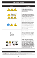
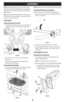
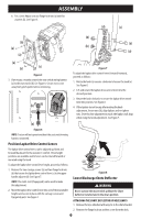
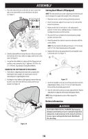
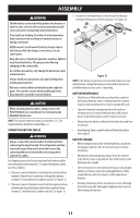
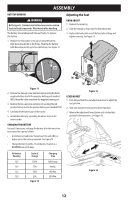
ASSEMBLY BATTERY REMOVAL WARNING Battery posts, terminals and related accessories contain lead and lead compounds. Wash hands after handling. The battery is located beneath the seat frame. To remove the battery: 1. Remove the hex washer screw (a) securing the battery hold-down bracket (b) to the frame. Then flip the battery hold-down bracket (b) up to free the battery. See Figure 13. Adjusting the Seat KNOB ADJUST 1. Remove the knobs (a). 2. Slide the seat up or down into the desired position. 3. Replace the knobs into one of the four hole settings and tighten securely. See Figure 15. (a) (b) Figure 13 2. Remove the hex cap screw and sems nut securing the black negative battery lead to the negative battery post (marked NEG). Move the cable away from the negative battery post. 3. Remove the hex cap screw and sems nut securing the red positive battery lead to the positive battery post (marked POS). 4. Carefully lift the battery out of the tractor. 5. Install the battery by repeating the above steps in the reverse order. CHARGING THE BATTERY Test and, if necessary, recharge the battery after the tractor has been stored for a period of time. • A voltmeter or load tester should read 12.6 volts (DC) or higher across the battery terminals. See Figure 14. • Charge the battery with a 12-volt battery charger at a MAXIMUM rate of 10 amps. (a) (a) Figure 15 LEVER ADJUST 1. Push left and hold the seat adjustment lever to adjust the seat position. 2. Slide seat forward or rearward to desired position. 3. Release the adjustment lever. Ensure seat is locked into position before operation. See Figure 16. Voltmeter Reading 12.7 12.4 12.2 12.0 State of Charge 100% 75% 50% 25% Figure 14 Charging Time Full Charge 90 Min. 180 Min. 280 Min. Figure 16 12
-
 1
1 -
2
-
3
-
4
-
5
-
6
-
 7
7 -
 8
8 -
 9
9 -
 10
10 -
 11
11 -
 12
12 -
 13
13 -
 14
14 -
 15
15 -
 16
16 -
 17
17 -
18
-
19
-
20
-
21
-
22
-
23
-
24
-
25
-
26
-
27
-
28
-
29
-
30
-
31
-
32
-
33
-
34
-
35
-
36
-
37
-
38
-
39
-
40
-
41
-
42
-
43
-
44
-
45
-
46
-
47
-
48
-
49
-
50
-
51
-
52
-
53
-
54
-
55
-
56
-
57
-
58
-
59
-
60
-
61
-
62
-
63
-
64
-
65
-
66
-
67
-
68
-
69
-
70
-
71
-
72
-
73
-
74
-
75
-
76
-
77
-
78
-
79
-
80
-
81
-
82
-
83
-
84
-
85
-
86
-
87
-
88
-
89
-
90
-
91
-
92
-
93
-
94
-
95
-
96
-
97
-
98
-
99
-
100
-
101
-
102
-
103
-
104
-
105
-
106
-
107
-
108
 |
 |
