Cub Cadet ZT1 50 Operation Manual - Page 9
Position Lapbar Drive Control Levers, Lower Discharge Chute Deflector
 |
View all Cub Cadet ZT1 50 manuals
Add to My Manuals
Save this manual to your list of manuals |
Page 9 highlights
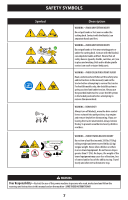
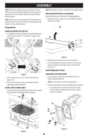
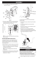
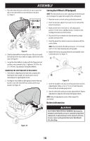
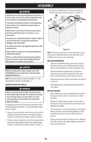
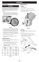
ASSEMBLY b. For a Lever Adjust seat use flange lock nuts (a) and flat washers (b). See Figure 5. (d) (c) (b) (a) (b) (a) (b) (a) (b) (a) (a) (a) (c) Figure 5 3. If necessary, securely connect the seat switch wiring harness (a) to the seat switch (b). See Figure 6. Secure excess wire away from pinch points before continuing. (b) (b) (a) Figure 7 To adjust the lapbar drive control levers forward/rearward, proceed as follows: 1. Rotate the knob (a) counter-clockwise to loosen the knob (a). See Figure 8. 2. Lift and rotate the lapbar drive control lever into the desired position. 3. Rotate the knob clockwise to secure the lapbar drive control lever into position. See Figure 8. 4. If the lapbars do not line up after making the knob adjustment, loosen nuts (b), align lapbars and re-tighten nuts. Once this fine adjustment is made, the lapbars will align when using the knob adjustment. See Figure 7. (a) Figure 6 NOTE: Tractor will not operate without the seat switch wiring harness connected. Position Lapbar Drive Control Levers The lapbar drive control levers can be adjusted up/down and forward/backward for the operator's comfort. Three height positions are available and/or levers can be rotated forward or rearward using the knob. (a) To adjust the lapbar drive control lever height, proceed as follows: 1. Remove the two carriage screws (a) and two flange lock nuts (b) that secure the lapbar drive control lever (c) to the upper handle adjuster (d). See Figure 7. NOTE: The multi-tool (if equipped) can be used to make this adjustment. 2. Move the lapbar drive control lever into one of three available heights and secure in place with the carriage screws and flange lock nuts. See Figure 7. Figure 8 Lower Discharge Chute Deflector WARNING Never operate the mower deck without the chute deflector installed and in the down position. ATTACHING THE CHUTE DEFLECTOR (IF NECESSARY) 1. Remove the keys attached with a zip tie to the chute bracket. 2. Remove the flange lock nut and hex screw from the deck. 9
-
 1
1 -
2
-
3
-
 4
4 -
 5
5 -
 6
6 -
 7
7 -
 8
8 -
 9
9 -
 10
10 -
 11
11 -
 12
12 -
 13
13 -
 14
14 -
15
-
16
-
17
-
18
-
19
-
20
-
21
-
22
-
23
-
24
-
25
-
26
-
27
-
28
-
29
-
30
-
31
-
32
-
33
-
34
-
35
-
36
-
37
-
38
-
39
-
40
-
41
-
42
-
43
-
44
-
45
-
46
-
47
-
48
-
49
-
50
-
51
-
52
-
53
-
54
-
55
-
56
-
57
-
58
-
59
-
60
-
61
-
62
-
63
-
64
-
65
-
66
-
67
-
68
-
69
-
70
-
71
-
72
-
73
-
74
-
75
-
76
-
77
-
78
-
79
-
80
-
81
-
82
-
83
-
84
-
85
-
86
-
87
-
88
-
89
-
90
-
91
-
92
-
93
-
94
-
95
-
96
-
97
-
98
-
99
-
100
-
101
-
102
-
103
-
104
-
105
-
106
-
107
-
108
 |
 |
