D-Link DCS-6510 User Manual - Page 8
Preparing for Installation - surface mount
 |
UPC - 790069340055
View all D-Link DCS-6510 manuals
Add to My Manuals
Save this manual to your list of manuals |
Page 8 highlights
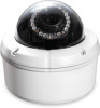
Installation Preparing for Installation A. Depending on how you choose to mount the camera, you may need to change the orientation of the cable. For instance, when using the Surface Mounting Bracket, the cables may need to exit through the side of the camera base rather than the top. Changing Cable Orientation: 1. Disassemble the camera enclosure. (See Figure A. on page 6.) 2. Loosen, but do not remove, the two screws that secure the camera bracket to the base of the enclosure using a screwdriver. (Figure 1.) Figure 1. 3. Slide the camera bracket towards the front of the camera base. (Figure 2.) 4. Lift the camera bracket off of the base and out of the way. (Figure 3.) 5. Disconnect the cables from the circuit board at the base of the camera. (Figure 4.) D-Link DCS-6510 User Manual Figure 3. Figure 2. Figure 4. 8
-
 1
1 -
2
-
 3
3 -
 4
4 -
 5
5 -
 6
6 -
 7
7 -
 8
8 -
 9
9 -
 10
10 -
 11
11 -
 12
12 -
 13
13 -
14
-
15
-
16
-
17
-
18
-
19
-
20
-
21
-
22
-
23
-
24
-
25
-
26
-
27
-
28
-
29
-
30
-
31
-
32
-
33
-
34
-
35
-
36
-
37
-
38
-
39
-
40
-
41
-
42
-
43
-
44
-
45
-
46
-
47
-
48
-
49
-
50
-
51
-
52
-
53
-
54
-
55
-
56
-
57
-
58
-
59
-
60
-
61
-
62
 |
 |
